Where are the Fuse Boxes located in the 2014 Hyundai Tucson?
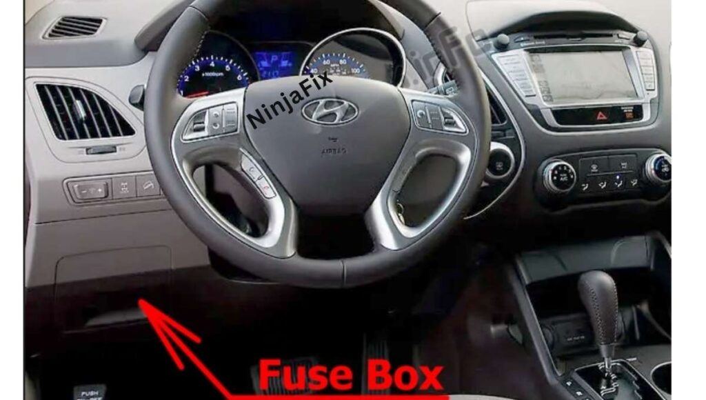
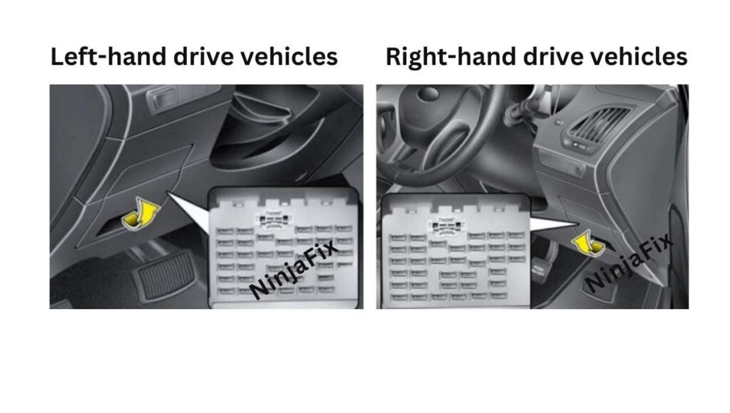
2014 Hyundai Tucson has 2 main boxes with fuses and relays. One is in the cabin (Passenger Compartment) and another is under the hood (Engine Compartment).
2014 Hyundai Tucson Under Dash Fuse Box and Relay Location
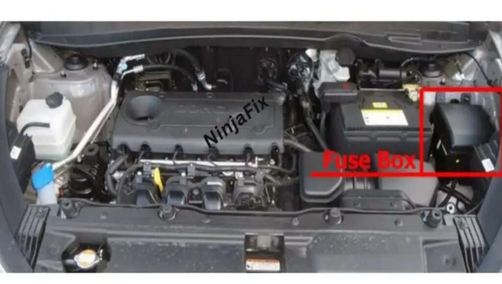
2014 Hyundai Tucson Under Hood Fuse Box and Relay location
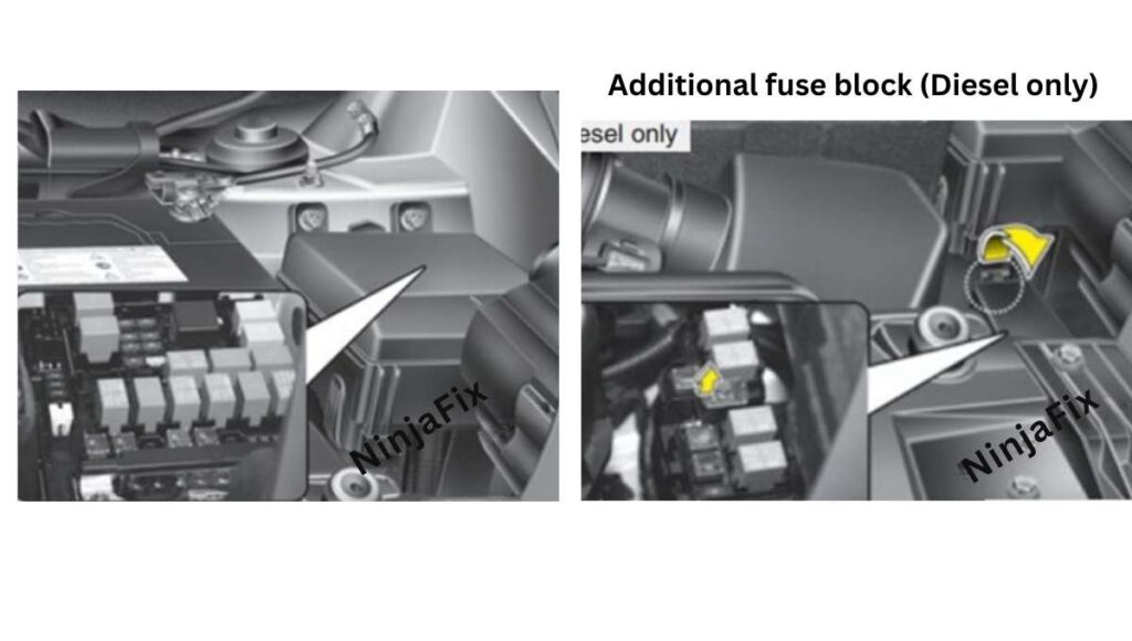
Battery Terminal(main fuse)
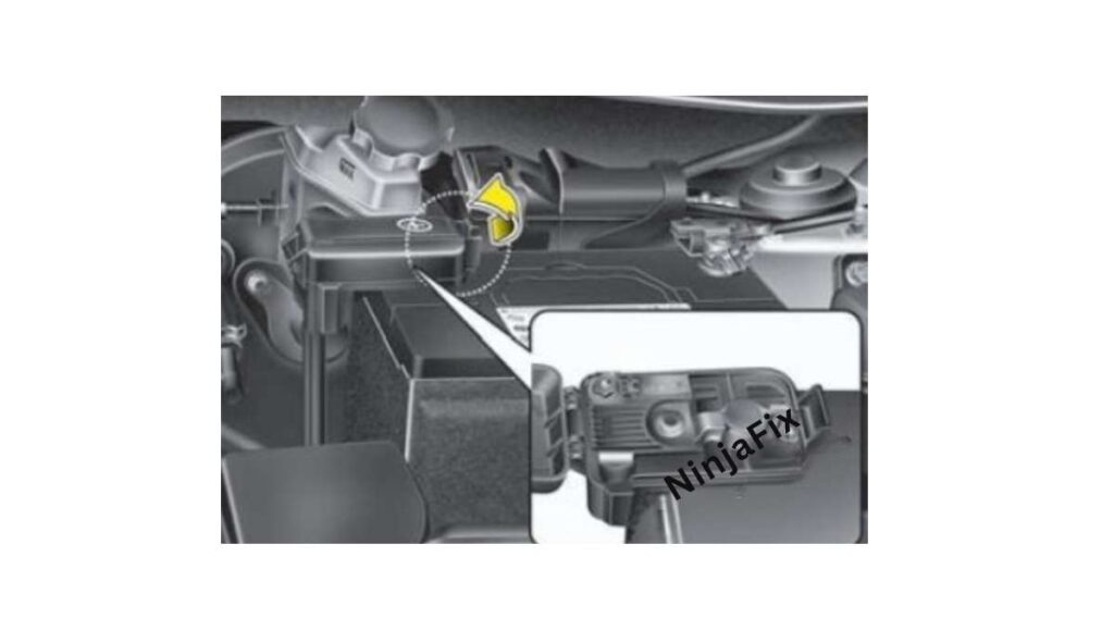
The Engine compartment fuse block is in the engine compartment is located on the driver side of the vehicle.
2014 Hyundai Tucson under Dash Fuse Box Layout
2014 Hyundai Tucson Under Dash Fuse Box Diagram
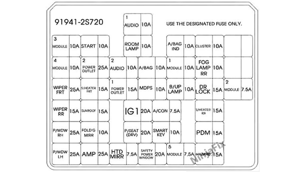
2014 Hyundai Tucson under Dash Fuse Box and Relay Details
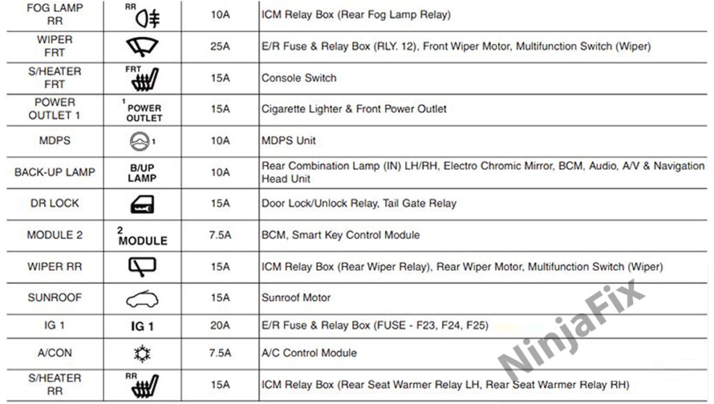
Assignment of the fuses and relays in the Passenger compartment,(Version-1)
| Description | Amp rating(A) | Protected component |
|---|---|---|
| POWER CONNECTOR (AUDIO 1) | 10A | Audio, A/V & Navigation Head Unit, MTS Module |
| POWER CONNECTOR (ROOM LAMP) | 10A | BCM, Auto Light & Photo Sensor, Date Link Connector, Ignition Key Illumination & Door Warning Switch, A/ C Control Module, Luggage Lamp, IPS Control Module, Instrument Cluster (Indicator), Electro Chromic Mirror, Engine Room Fuse & Relay Box (Interior Lamp Relay) |
| MODULE 3 | 10A | IPS Control Module, BCM, Electro Chromic Mirror, Smart Key Control Module, ICM Relay Box (Rear Seat Heater Left/Right Relay) |
| START | 10A | [W/O Immobilizer] Burglar Alarm Relay [With Immobilizer] Engine Room Fuse & Relay Box (Start Relay) |
| A/BAG IND | 10A | Instrument Cluster (Air Bag Indicator) |
| CLUSTER | 10A | Audio, Console Switch, Instrument Cluster (Indicator), BCM, Alternator, A/V & Navigation Head Unit, MTS Module, Electro Chromic Mirror, A/C Control Module |
| MODULE 4 | 10A | Engine Room Fuse & Relay Box (Blower Relay, Head Lamp High Relay), Cluster Ionizer, A/C Control Module, Sunroof Motor |
| POWER OUTLET 2 | 25A | Cigarette Lighter & Front Power Outlet, Rear Power Outlet |
| AUDIO 2 | 10A | Power Outside Mirror Switch, AMP, BCM, A/V & Navigation Head Unit, Audio, MTS Module, Smart Key Control Module |
| A/BAG | 10A | SRS Control Module, Passenger Occupant Detection Sensor, Telltale Lamp |
| MODULE 1 | 10A | IPS Control Module, Tire Pressure Monitoring Module, ESC Off Switch, ATM Shift Lever Indicator, DBC Switch, Multifunction Switch (Light), Stop Lamp Switch, 4WD ECM |
| FOG LAMP RR | 10A | – |
| WIPER FRT | 25A | Front Wiper Motor, Multifunction Switch (Wiper), Engine Room Fuse & Relay Box (Wiper Front, Low Relay) |
| S/HEATER FRT | 15A | Console Switch |
| POWER OUTLET 1 | 15A | Cigarette Lighter & Front Power Outlet |
| MDPS | 10A | MDPS Unit |
| B/UP LAMP | 10A | BCM, Audio, Electro Chromic Mirror, Rear Combination Lamp (IN) Left/Right, A/V & Navigation Head Unit |
| DR LOCK | 15A | Door Lock Relay, Tail Gate Relay, Door Unlock Relay, ICM Relay Box (Two Turn Unlock Relay) |
| MODULE 2 | 7.5A | BCM, Smart Key Control Module |
| WIPER RR | 15A | ICM Relay Box (Rear Wiper Relay), Rear Wiper Motor, Multifunction Switch (Wiper) |
| SUNROOF | 15A | Sunroof Motor |
| IG 1 | 20A | Engine Room Fuse & Relay Box(ECU 2 7.5A, ABS 3 7.5A, TCU 2 7.5A) |
| A/CON | 7.5A | A/C Control Module |
| S/HEATER RR | 15A | ICM Relay Box (Rear Seat Heater Left/Right Relay) |
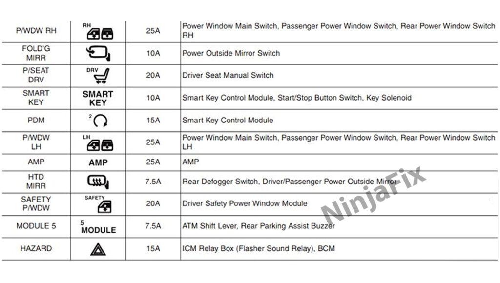
| P/WDW RH | 25A | Power Window Main Switch, Passenger Power Window Switch, Rear Right Power Window Switch |
| FOLD’G MIRR | 10A | – |
| P/SEAT (DRV) | 20A | Driver Seat Manual Switch |
| SMART KEY | 10A | Smart Key Control Module, Engine Start/Stop Button |
| PDM | 15A | Smart Key Control Module |
| P/WDW LH | 25A | Power Window Main Switch, Rear Left Power Window Switch |
| AMP | 25A | AMP |
| HTD MIRR | 7.5A | Rear Defogger Switch, Driver/Passenger Power Outside Mirror |
| SAFETY POWER WINDOW | 20A | Driver Safety Power Window Module |
| MODULE 5 | 7.5A | ATM Shift Lever, Tire Pressure Monitoring Module |
| HAZARD | 15A | ICM Relay Box (Flasher Sound Relay), BCM |
Assignment of the fuses in the instrument panel (Version-2)
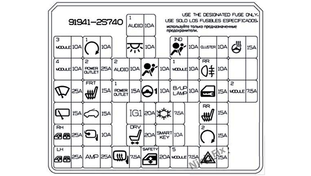
Assignment of the fuses in the instrument panel,(Version-2)
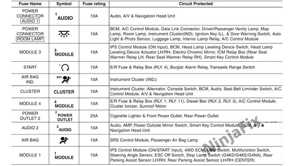
2014 Hyundai Tucson Under Hood Fuse Box Layout
2014 Hyundai Tucson Under Hood Fuse Box Diagram
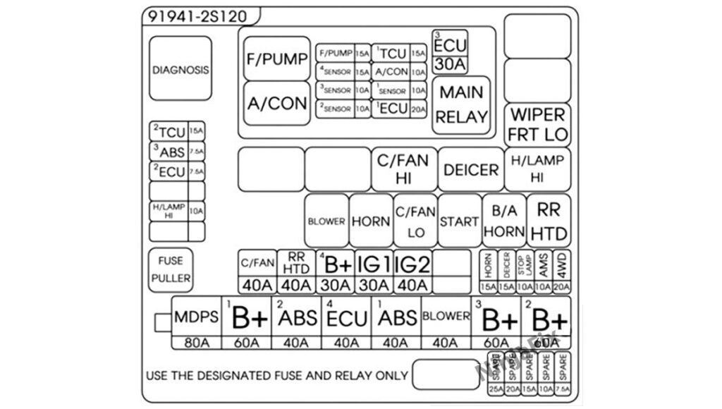
2014 Hyundai Tucson under Hood Fuse Box and Relay Details
Assignment of the fuses and relays in the Engine compartment,(Version-1)
| Description | Amp rating(A) | Protected component |
|---|---|---|
| MULTI FUSE: | ||
| MDPS | 80A | MDPS Unit |
| B+1 | 60A | Smart Junction Box (DR LOCK 15A, HAZARD 15A, PDM 15A, S/HEATER RR 15A) |
| ABS 2 | 40A | Multipurpose Check Connector, ESC Module |
| ECU 4 | 40A | EMS Box (TCU 1 15A, ECU 3 30A, A/CON 10A, F/PUMP 15A) |
| ABS 1 | 40A | Multipurpose Check Connector, ESC Module |
| BLOWER | 40A | Blower Relay |
| B+3 | 60A | Smart Junction Box (P/SEAT(DRV) 20A, SAFETY POWER WINDOW 20A, SMART KEY 10A, MODULE 5 7.5A, Power Connector (AUDIO 1 10A, ROOM LAMP 10A), IPS-1CH, IPS-2CH) |
| B+2 | 60A | Smart Junction Box (Power Window Relay, SUNROOF 15A, AMP 25A, IPS-1CH) |
| FUSE: | ||
| C/FAN | 40A | Engine Room Fuse & Relay Box (C/FAN LO Relay, C/FAN HI Relay) |
| RR HTD | 40A | Engine Room Fuse & Relay Box (RR HTD Relay) |
| B+ 4 | 30A | Engine Room Fuse & Relay Box (H/LAMP HI 10A) |
| IG 1 | 30A | Ignition Switch, PDM Relay Box (IGN 1 Relay) |
| IG 2 | 40A | Engine Room Fuse & Relay Box (Start Relay), Ignition Switch, PDM Relay Box (IGN 2 Relay) |
| HORN | 15A | Engine Room Fuse & Relay Box (Horn Relay, B/A Horn Relay) |
| DEICER | 15A | Engine Room Fuse & Relay Box (Deicer Relay) |
| STOP LAMP | 10A | Stop Lamp Switch, Stop Signal Electric Module, Smart Key Control Module |
| AMS | 10A | Battery Sensor |
| 4WD | 20A | 4WD ECM |
| H/LAMP HI | 10A | Engine Room Fuse & Relay Box (H/LAMP HI Relay) |
| ECU 2 | 7.5A | PCM/ECM, Clock Spring |
| ABS 3 | 7.5A | Multipurpose Check Connector, ESC Module |
| TCU 2 | 15A | Transaxle Range Switch (A/T), Vehicle Speed Sensor (M/T), Back-up Lamp Switch (M/T) |
| F/PUMP | 15A | EMS Box(F/PUMP Relay) |
| SENSOR 4 | 15A | E/R Fuse & Relay Box(C/FAN HI, LO Relay), EMS Box(F/PUMP Relay), Oxygen Sensor (Up, Down) |
| SENSOR 3 | 10A | EMS Box (A/CON Relay) |
| SENSOR 2 | 10A | (Not Used) |
| SENSOR 1 | 10A | PCM |
| TCU 1 | 15A | EMS Box (A/CON Relay) |
| A/CON | 10A | Immobilizer Module, Crankshaft Position Sensor, Camshaft Position Sensor #1/2, Oil Control Valve #1/2, Purge Control Solenoid Valve, Variable Intake Manifold Valve, Canister Close Valve |
| ECU 1 | 20A | Ignition Coil (#1, #2, #3, #4), Condenser |
| ECU 3 | 30A | EMS Box(Engine Control Relay) |
Assignment of the relays,(Version 2)
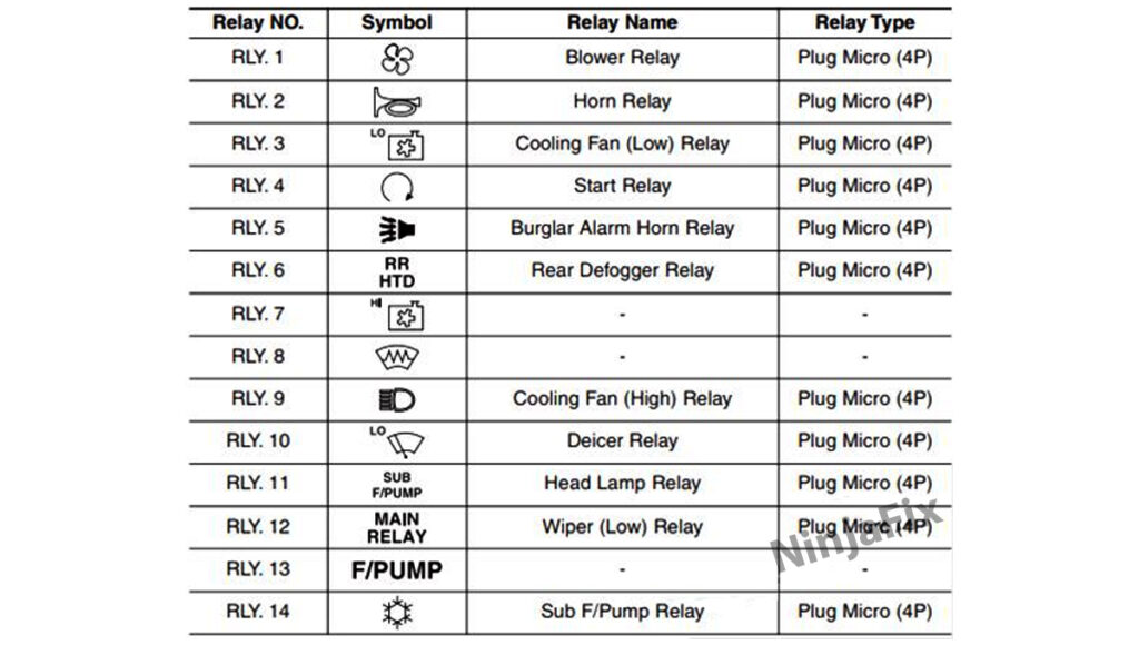
Assignment of the fuses in the Engine compartment,(Version 2)
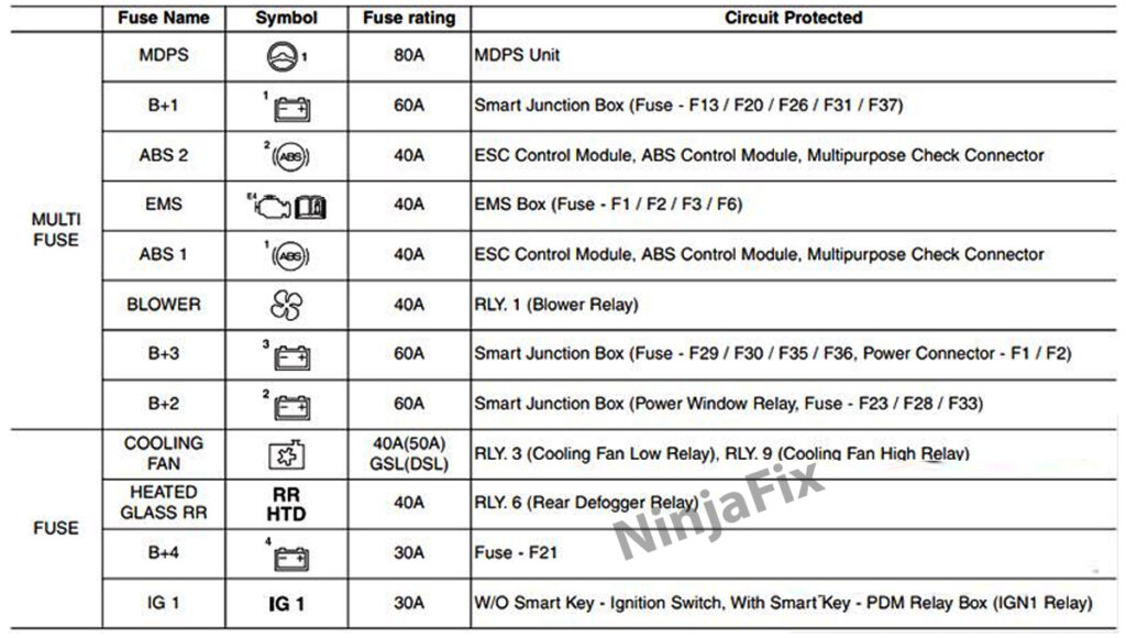
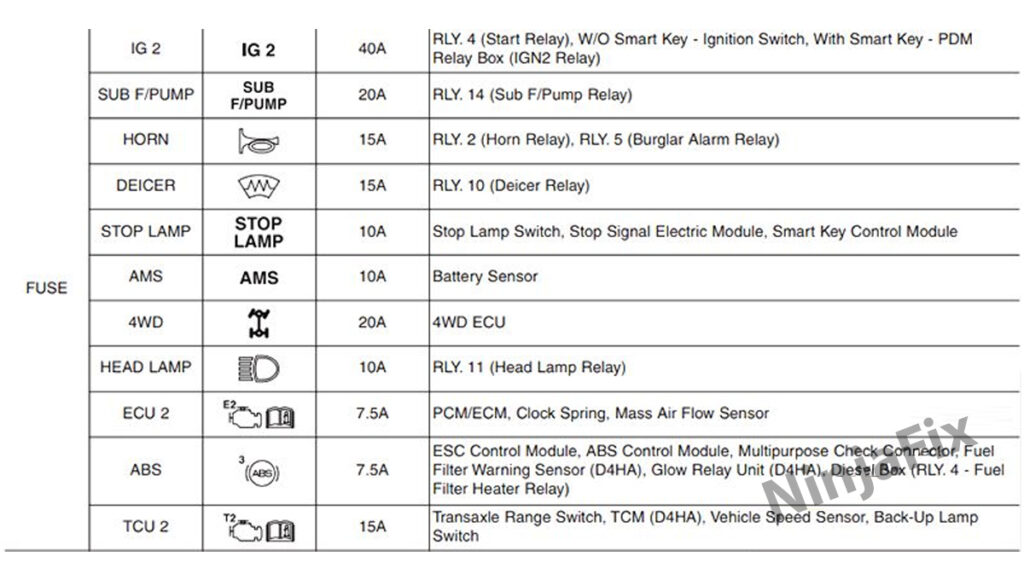
Engine compartment fuse panel,(Diesel engine only)(Version 2)
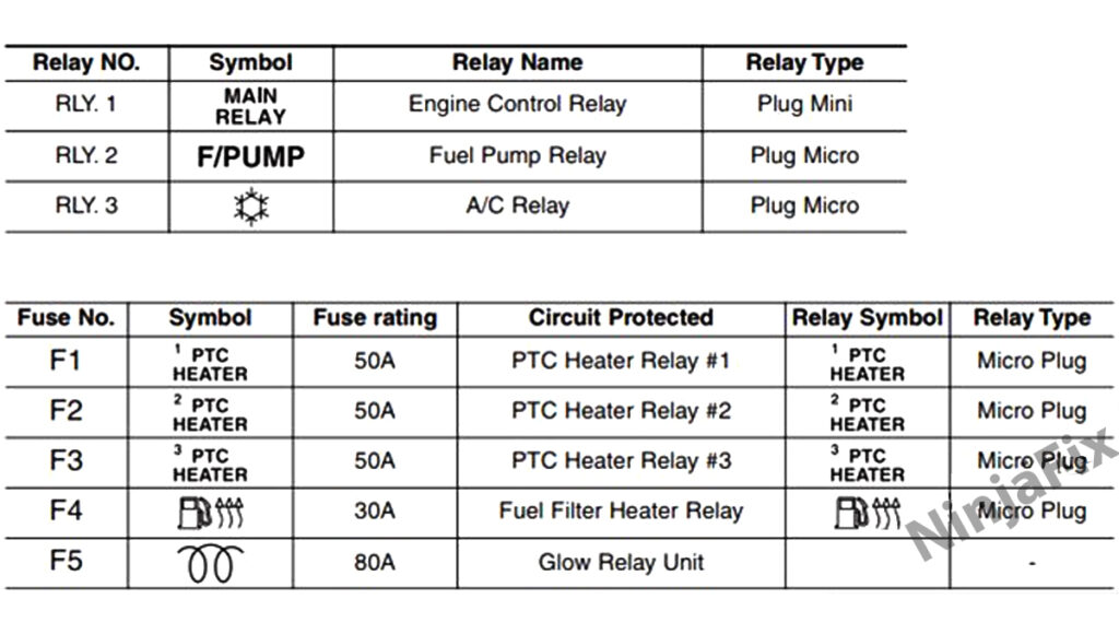
Circuit (EMS Box) – G4KE/G4KJ : THETA II 2.4L MPI/GDI (Version 2)
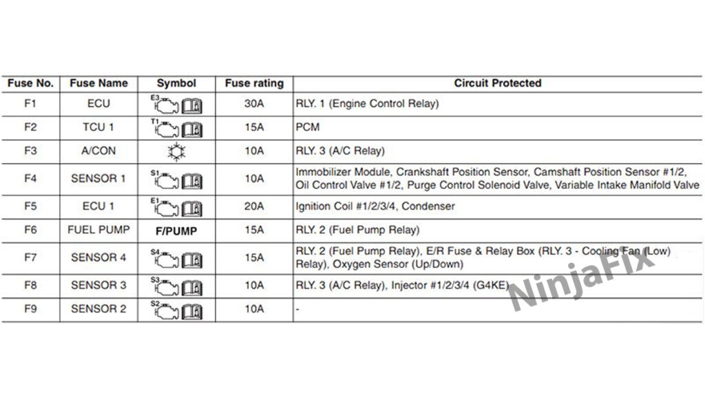
Circuit (EMS Box) – G4NA/G4NC : NU 2.0L MPI/GDI (Version 2)
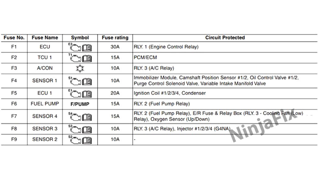
Circuit (EMS Box) – D4HA : R 2.0L (Version 2)
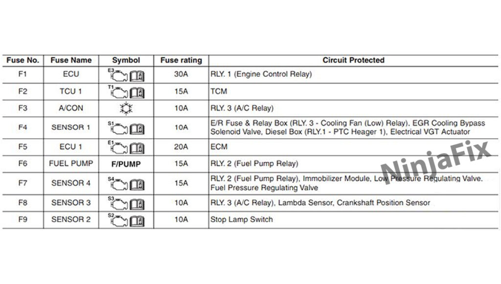
WARNING: The terminal and harness assignments for individual connectors may vary depending on the vehicle’s equipment level, model, and market. It is recommended to refer to the fuse box diagram provided at the back of the fuse box cover for accurate information.

