Where are the Fuse Boxes located in the 2017 Honda CR-V?
2017 Honda CR-V has 2 main boxes with fuses and relays. One is in the cabin (Passenger Compartment) and another is under the hood (Engine Compartment).
2017 Honda CR-V Under Dash Fuse Box and Relay Location
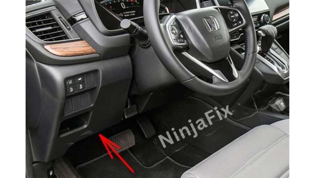
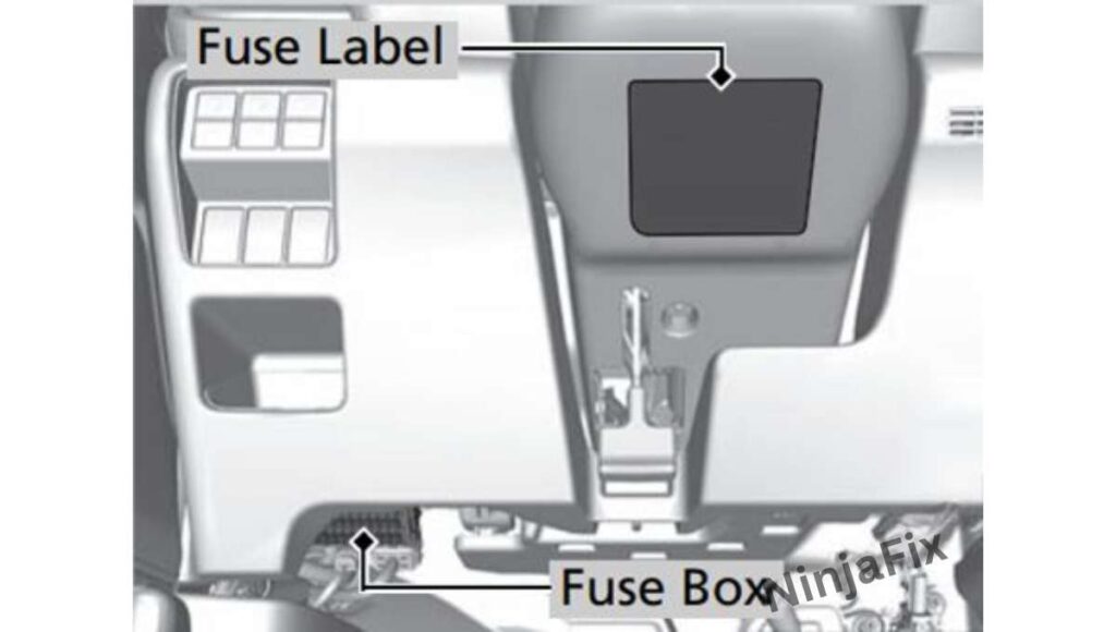
The interior fuse box is located under the dashboard on the driver’s side. The fuse label is attached under the steering column.
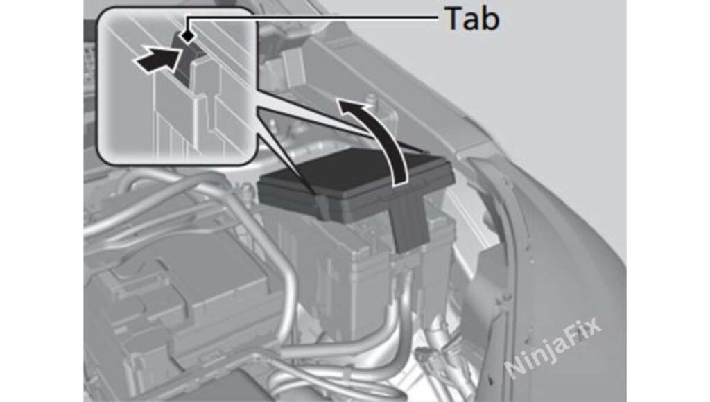
The auxiliary fuse box (If equipped) is located next to the interior fuse box. To open the lid, pull the tab in the direction as shown in the illustration.
The auxiliary fuse box (If equipped) is located next to the interior fuse box. To open the lid, pull the tab in the direction as shown in the illustration.
2017 Honda CR-V Under Hood Fuse Box and Relay location
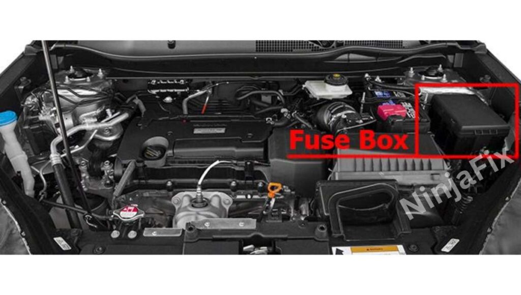
The Engine compartment fuse block is in the engine compartment is located on the driver side of the vehicle near the brake fluid reservoir.
2017 Honda CR-V under Dash Fuse Box Layout
2017 Honda CR-V Under Dash Fuse Box Diagram
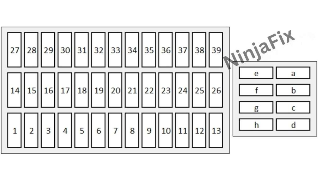
2017 Honda CR-V under Dash Fuse Box and Relay Details
Assignment of the fuses in the Passenger Compartment
| No. | Circuit Protected | Amps |
|---|---|---|
| 1 | Accessory | 10 A |
| 2 | Key Lock | 5 A |
| 3 | Option | 10 A |
| 4 | Option (with smart entry system) | 5 A |
| 4 | Transmission (without smart entry system) (1.5L) | (10 A) |
| 5 | Option | 10 A |
| 6 | SRS Indicator | 10 A |
| 7 | Meter | 10 A |
| 8 | Fuel Pump | 15 A |
| 9 | A/C | 10 A |
| 10 | Accessory Power Socket (Center Console) | (20 A) |
| 11 | Engine Control’ 3 | 5 A |
| 12 | Passenger’s Side Door Lock | 10 A |
| 13 | Driver’s Side Door Unlock | 10 A |
| 14 | Rear Driver’s Side Power Window | 20 A |
| 15 | Front Passenger’s Side Power Window | 20 A |
| 16 | Door Lock | 20 A |
| 17 | Transmission (with smart entry system) (1.5L) | (10 A) |
| 17 | Option (without smart entry system) | 5 A |
| 18 | Front Driver’s Lumber support (option) | (10 A) |
| 19 | Moonroof (option) | (20 A) |
| 20 | Starter | 10 A |
| 21 | ACG | 10 A |
| 22 | Daytime Running Light | 10 A |
| 23 | Steering Wheel Heater (Canadian models with steering heater) ; Handsfree Power Tailgate Sensor (option) | (10 A) |
| 24 | Option | 5 A |
| 25 | Driver’s Door Lock | (10 A) |
| 26 | Passenger’s Side Door Unlock | 10 A |
| 27 | Rear Passenger’s Side Power Window | 20 A |
| 28 | Driver’s Power Window | 20 A |
| 29 | Front Accessory Power Socket | 20 A |
| 30 | Smart Entry (Canadian models with steering heater) | 10 A |
| 30 | STS (without smart entry system) | 5 A |
| 31 | Driver’s Power Seat Reclining (option) | (20 A) |
| 32 | Front Seat Heater (option) | (20 A) |
| 33 | Driver’s Power Seat Sliding (option) | (20 A) |
| 34 | ABS/VSA | 10 A |
| 35 | SRS | 10 A |
| 36 | HAC Option (option) | 20 A |
| 37 | Trailer (option) | 15 A |
| 38 | Driver’s Side Door Lock | 10 A |
| 39 | Driver’s Door Unlock | (10 A) |
| a | Power Tailgate Closer (option) | (20 A) |
| b | Passenger’s Power Seat Sliding (option) | (20 A) |
| c | Passenger’s Power Seat Reclining (option) | (20 A) |
| d | Panorama Shade Motor (Canadian models with panoramic roof) | (20 A) |
| e | Rear Blower | (20 A) |
| f | EPT L | (20 A) |
| g | EPT R | (20 A) |
| h | Accessory Power Socket (Cargo Area) (Canadian models) | (20 A) |
2017 Honda CR-V Under Hood Fuse Box Layout
2017 Honda CR-V Under Hood Fuse Box Diagram
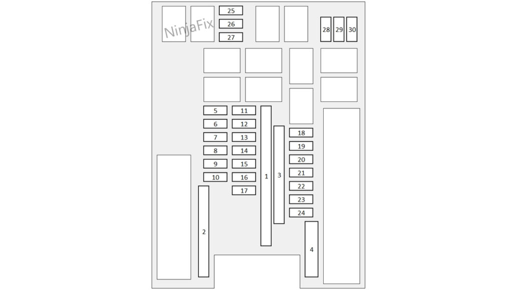
2017 Honda CR-V under Hood Fuse Box and Relay Details
Assignment of the fuses in the Engine compartment
| No. | Circuit Protected | Amps |
|---|---|---|
| 1 | Audio AMP (optoin) | (30 A) |
| 1 | Electric Brake Booster | 40 A |
| 1 | Main Fan Motor | 30 A |
| 1 | Relay Module 1 | 30 A |
| 1 | IG Main 2 (with smart entry system) | 30 A |
| 1 | Relay Module 2 | 30 A |
| 1 | Battery | 125 A |
| 2 | EPS | 70 A |
| 2 | IG Main 1 (30 A (with smart entry system) / 50 A (without smart entry system)) | 30 A / 50 A |
| 2 | Fuse Box Option | (40 A) |
| 2 | Fuse Box | 60 A |
| 2 | Front Wiper Motor | 30 A |
| 2 | Sub Fan Motor | 30 A |
| 3 | Rear Defroster | 40 A |
| 3 | Starter Motor | 30 A |
| 3 | Fuse Box | 40 A |
| 3 | ABS/VSA Motor | 40 A |
| 3 | ABS/VSA FSR | 40 A |
| 3 | Blower Motor | 40 A |
| 4 | Option Block 1 (optoin) | (40 A) |
| 4 | Option Block 2 (optoin) | (40 A) |
| 4 | – | – |
| 4 | Power Tail Gate (optoin) | (40 A) |
| 5 | VB ACT (1.5L) | (7.5 A) |
| 6 | Washer | 15 A |
| 7 | FI Main | 15 A |
| 8 | FI Sub (1.5L) / DBW (2.4L) | 15 A |
| 9 | Stop Lights | 10 A |
| 10 | Injector | 20 A |
| 11 | LAF | 7.5 A |
| 12 | FI ECU (1.5L) | 10 A |
| 12 | – (2.4L) | – |
| 13 | Front Wiper Deicer (optoin) | (15 A) |
| 14 | Hazard | 10 A |
| 15 | IG Coil | 15 A |
| 16 | Transmission (1.5L) | (15 A) |
| 16 | – (2.4L) | – |
| 17 | — | — |
| 18 | Back Up | 10 A |
| 19 | Audio | 15 A |
| 20 | AWD (optoin) | (20 A) |
| 21 | Rear Seat Heater (Canadian models with rear seat heater) | (20 A) |
| 21 | – (without rear seat heater) | – |
| 22 | Front Fog Lights (Models with fog lights) / Lower Shutter Grille | (15 A) |
| 23 | A/C Compressor / Upper Shutter Grille | 10 A |
| 24 | Horn | 10 A |
| 25 | Cooling Fan | 7.5 A |
| 26 | – | — |
| 27 | – | — |
| 28 | ST Magnetic Switch (without smart entry system) | (7.5 A) |
| 29 | – | — |
| 30 | – | — |
WARNING: The terminal and harness assignments for individual connectors may vary depending on the vehicle’s equipment level, model, and market. It is recommended to refer to the fuse box diagram provided at the back of the fuse box cover for accurate information.
