The fuse box diagram for your Ford F-150 is a valuable resource, providing crucial details about the location and function of each fuse, enabling effective troubleshooting of electrical issues. However, owning a Ford F-150 entails much more than just dealing with electrical problems. As a proud owner, it’s essential to equip yourself with all the necessary information about your Ford F-150 to fully maximize your ownership experience.
Where are the fuse boxes located?
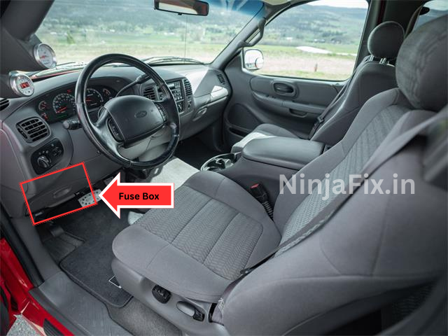
- Passenger Compartment : The fuse panel is located below and to the left of the steering wheel by the brake pedal behind the cover.
- Engine Compartment Fuse Box: The power distribution box is located in the engine compartment (left-side).
1. Passenger Compartment
2. Engine Compartment Fuse Box
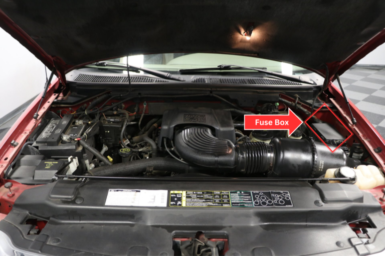
2002 Ford F 150 Fuse Box Diagram
Passenger Compartment
2002 Ford F 150 Passenger Compartment Fuse Box Diagram
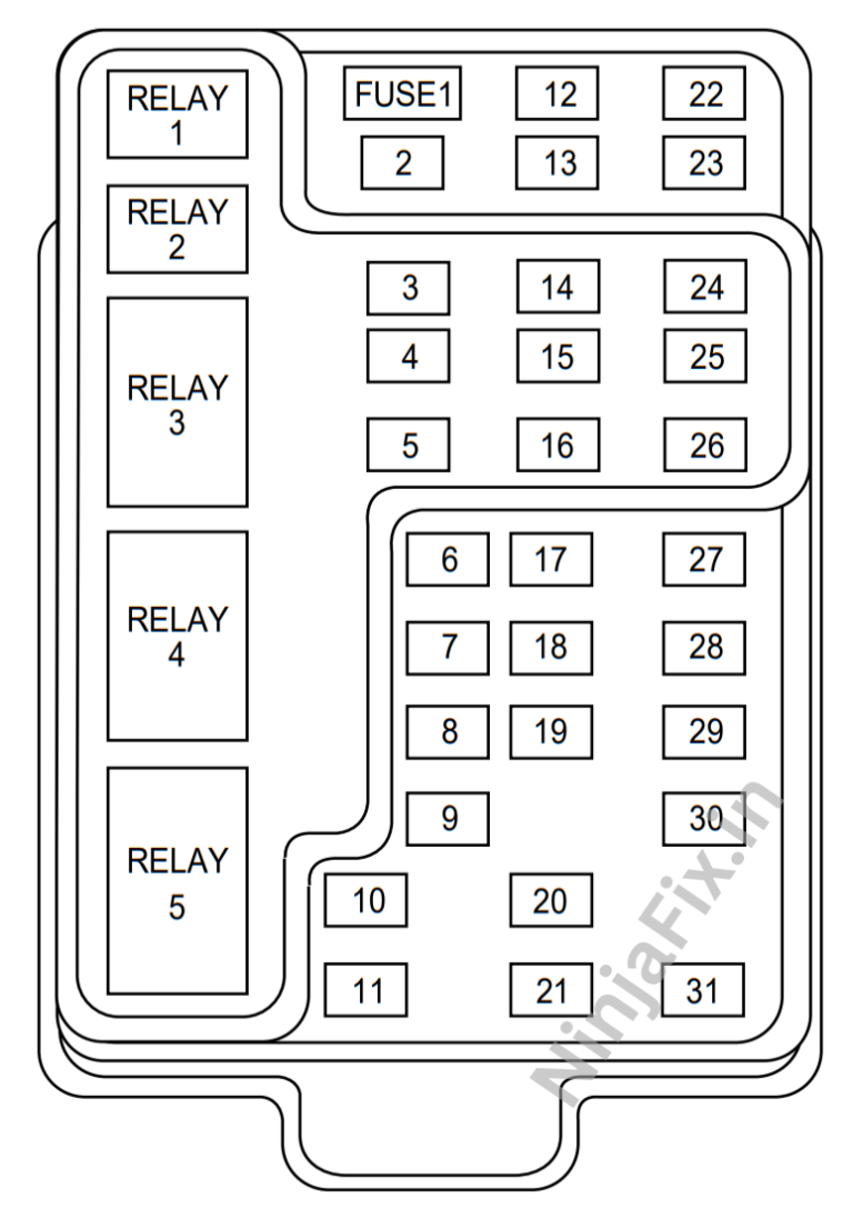
2002 Ford F 150 Passenger Compartment Fuse Details
| № | Fuse Function |
|---|---|
| 1 | Audio |
| 2 | Powertrain Control Module (PCM), Cluster |
| 3 | Cigar Lighter, OBD-II Scan Tool Connector |
| 4 | Power mirror switch, Mirror turn signal relays |
| 5 | Speed Control Module, Reverse Lamp, Climate Mode Switch, Daytime Running Lamp Relay |
| 6 | Cluster, Brake Shift Interlock Solenoid, GEM Module |
| 7 | Not Used |
| 8 | Radio, Remote entry module, GEM, In-vehicle entertainment system (SuperCrew only) |
| 9 | Not Used |
| 10 | Not Used |
| 11 | Front Washer Pump Relay, Wiper Run/Park Relay, Wiper Hi/LO Relay, Windshield Wiper Motor |
| 12 | Not Used |
| 13 | Stop lamp switch (Lamps), Turn/Hazard flasher |
| 14 | Battery saver relay, Interior lamp relay |
| 15 | Stop lamp switch (speed control, brake shift interlock), GEM, Rear Anti-lock Brake System (RABS) module |
| 16 | Headlamps (hi beams), Cluster (hi beam indicator) |
| 17 | Not Used |
| 18 | Instrument Illumination (Dimmer Switch Power) |
| 19 | Not Used |
| 20 | Audio, GEM, PCM, Transmission range sensor |
| 21 | DTR sensor, Clutch switch, Starter relay, I/P fuse 20 |
| 22 | Air bag module, Passenger air bag deactivation module |
| 23 | Trailer tow battery Charge relay, Turn/Hazard flasher, 4×4 solenoids, 4×4 relays, Overhead console, 4–Wheel Anti-lock Brake System (4WABS) module, EC mirror, Heated seats |
| 24 | Function selector switch assembly |
| 25 | Not Used |
| 26 | Right Side Low Beam Headlamp |
| 27 | Foglamp relay and foglamp indicator, Main light switch (upstream) |
| 28 | Left-hand low beam headlamp |
| 29 | Autolamp module, Transmission overdrive control switch, Central security module, Beltminder |
| 30 | Passive Anti-theft transceiver, Cluster, Ignition coils, PCM relay, Coil on plugs, Radio noise capacitor, ECC diode |
| 31 | Not Used |
| Relay 1 | Interior Lamp Relay |
| Relay 2 | Battery Saver Relay |
| Relay 3 | Not Used |
| Relay 4 | One Touch Down Window Relay |
| Relay 5 | ACC Delay Relay |
2002 Ford F 150 fuse box diagram under hood
2002 Ford F 150 Power Distribution Fuse Box Diagram
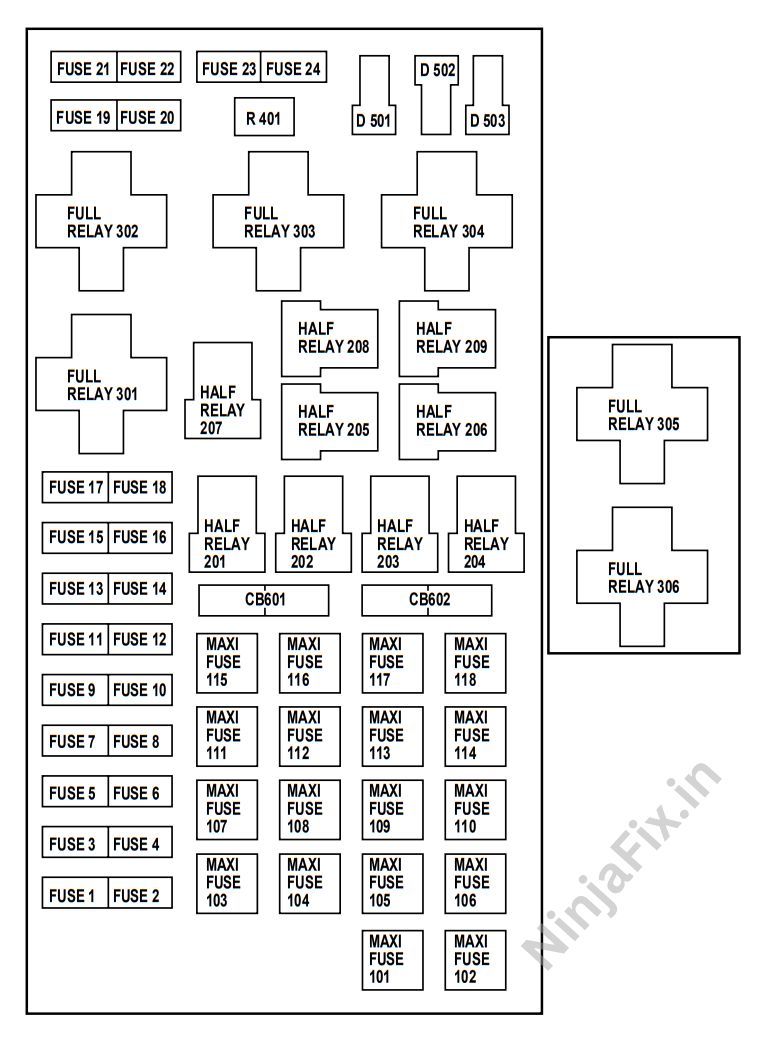
2002 Ford F 150 Power Distribution Fuse Box Details
| No | Fuse Function |
|---|---|
| 1 | Power Point |
| 2 | Powertrain Control Module |
| 3 | Main Light Switch, Headlamp Relay, Multifunction Switch |
| 4 | Not Used |
| 5 | Trailer Tow Backup/Park Lamps |
| 6 | Main Light Switch, Park Lamp Relay |
| 7 | Horn |
| 8 | Power door locks, Central Security Module (CSM), Lock relays (not used on SuperCrew) |
| 9 | Daytime Running Lamps (DRL), Fog Lamps. |
| 10 | Fuel Pump |
| 11 | Alternator Field |
| 12 | Rear auxiliary power point (SuperCrew only) |
| 13 | A/C Clutch |
| 14 | Not Used |
| 15 | Running board lamps |
| 16 | Not Used |
| 17 | Not Used |
| 18 | PCM, Fuel injectors, Fuel pump relay, Mass air flow sensor |
| 19 | Trailer/Camper Adapter (Right Stop and Right Turn Lamp) |
| 20 | Trailer/Camper Adapter (Left Stop and Left Turn Lamp) |
| 21 | Not Used |
| 22 | Not Used |
| 23 | HEGO sensor, Automatic transmission |
| 24 | Not Used |
| 101 | Trailer Tow Battery Charge |
| 102 | Four-wheel Anti-lock Brake System (4WABS) module/Rear-wheel Anti-lock Brake System (RABS) module, Ignition switch |
| 103 | Central junction box |
| 104 | 4×4 Shift Motor & Clutch |
| 105 | Climate Control Front Blower |
| 106 | Intercooler pump (supercharged engine only |
| 107 | Not Used |
| 108 | Trailer Tow Electric Brake |
| 109 | Not Used |
| 110 | Accessory delay relay (Not used on SuperCrew) |
| 111 | Ignition Switch Battery Feed (Start and Run Circuits) |
| 112 | Drivers Power Seat, Adjustable Pedals |
| 113 | Ignition Switch Battery Feed (Run and Accessory Circuits) |
| 114 | Not Used |
| 115 | Power Door Locks (Super Crew only) |
| 116 | Not Used |
| 117 | Not Used |
| 118 | Heated Seats |
| 201 | Trailer Tow Park Lamp Relay |
| 202 | Front Wiper Run/Park Relay |
| 203 | Trailer Tow Backup Lamp Relay |
| 204 | A/C Clutch Relay |
| 205 | Horn Relay |
| 206 | Fog Lamp Relay |
| 207 | Front Washer Pump Relay |
| 208 | Intercooler pump relay (supercharged engine only) |
| 209 | Front Wiper Hi/Lo Relay |
| 301 | Fuel Pump Relay |
| 302 | Trailer Tow Battery Charge Relay |
| 303 | Not Used |
| 304 | Powertrain Control Module Relay |
| 305 | Fuel pump HI/LO relay (supercharged engine only) |
| 306 | Inertia switch relay (supercharged engine only) |
| 401 | Not Used |
| 501 | PCM Diode |
| 502 | A/C Compressor Diode |
| 503 | Not Used |
| 601 | Power Windows, Moonroof (Super Crew only) |
| 602 | Not Used |
WARNING: The terminal and harness assignments for individual connectors may vary depending on the vehicle’s equipment level, model, and market. It is recommended to refer to the fuse box diagram provided at the back of the fuse box cover for accurate information.

