Where are the fuse boxes located?
- Passenger compartment fuse panel / power distribution box : The fuse panel is located under the right-hand side of the instrument panel.
- Engine Compartment Relay Box: The power distribution box is located in the engine compartment (left-side).
1. Passenger Compartment
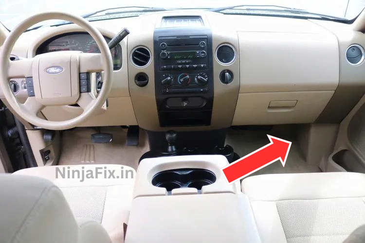
How to access fuse panel ?
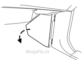
Remove the trim panel and fuse box cover to access the fuses.
To remove the trim panel for access to the fuse box, pull the panel toward you and swing it out away from the side and remove it. To reinstall it, line up the tabs with the
grooves on the panel, then push it shut.
2. Engine Compartment Fuse Box
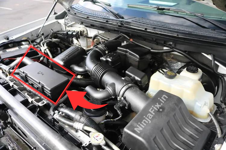
2009 Ford F 150 Fuse Box Diagram
Passenger Compartment Fuse Panel / Power Distribution Box
2009 Ford F 150 Passenger Compartment Fuse Box Diagram
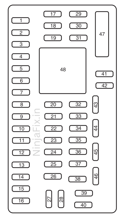
2009 Ford F 150 Passenger Compartment Fuse Details
| № | Amps | Fuse Function |
|---|---|---|
| 1 | 30A | Moon roof |
| 2 | 15A | Not used (spare) |
| 3 | 15A | Not used (spare) |
| 4 | 30A | Not used (spare) |
| 5 | 10A | Keypad illumination, Brake Shift Interlock (BSI), SJB microprocessor power |
| 6 | 20A | Turn signals, Stop lamps |
| 7 | 10A | Low beam headlamps (left) |
| 8 | 10A | Low beam headlamps (right) |
| 9 | 15A | Interior courtesy lights, Cargo lamps |
| 10 | 15A | Backlighting, Puddle lamps |
| 11 | 10A | Not used (spare) |
| 12 | 7.5A | Power mirror switch, Memory seat module microprocessor power, Steering column switch |
| 13 | 5A | SYNC |
| 14 | 10A | Not used (spare) |
| 15 | 10A | Climate control |
| 16 | 15A | Ignition switch feed |
| 17 | 20A | All lock motor feeds |
| 18 | 20A | Driver memory seat switch |
| 19 | 25A | Not used (spare) |
| 20 | 15A | Adjustable pedals, Datalink |
| 21 | 15A | Fog lamps, Fog lamp indicator |
| 22 | 15A | Park lamps, Side marker lamps |
| 23 | 15A | High beam headlamps |
| 24 | 20A | Horn |
| 25 | 10A | Interior demand lamps, Mid box power feed |
| 26 | 10A | Instrument panel cluster, Key out inhibit solenoid, Radio info display (CID), Radio buttons, Key-in chime |
| 27 | 20A | Not used |
| 28 | 5A | Radio muting |
| 29 | 5A | Instrument panel cluster |
| 30 | 5A | Passenger airbag disable indicator |
| 31 | 10A | Restraints control module |
| 32 | 10A | Non-integrated compass module, Heated-only seat module |
| 33 | 10A | Trailer brake controller |
| 34 | 5A | Electronic locking differential indicator |
| 35 | 10A | Rear park assist |
| 36 | 5A | PATS transceiver |
| 37 | 10A | Not used (spare) |
| 38 | 20A | Subwoofer |
| 39 | 20A | Radio, Navigation display |
| 40 | 20A | Not used (spare) |
| 41 | 15A | EC mirror, Door lock switch illumination, Radio accessory delay |
| 42 | 10A | Not used (spare) |
| 43 | 10A | Heated mirror/backlight relay, Rain sensor, Reverse camera |
| 44 | 10A | Not used (spare) |
| 45 | 5A | Front wiper logic, Blower motor relay |
| 46 | 7.5A | Occupant classification sensor (OCS) |
| 47 | 30A Circuit Breaker | Power windows, Moon roof, Power sliding backlight |
| 48 | — | Delayed accessoiy relay (Feeds fuse 41 and circuit breaker 47) |
2009 Ford F 150 Under Hood Fuse Panel
2009 Ford F 150 Under Hood Fuse Panel Diagram
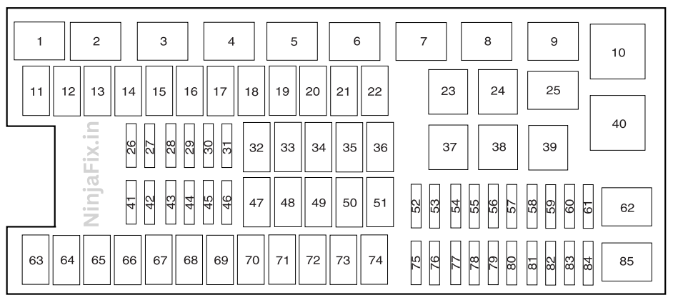
2009 Ford F 150 Under Hood Fuse Panel Diagram
| № | Amps | Fuse Function |
|---|---|---|
| 1 | — | PCM power relay |
| 2 | — | Starter relay |
| 3 | — | Blower motor relay |
| 4 | — | Heated backlite relay |
| 5 | — | Not used |
| 6 | — | Trailer tow park lamp relay |
| 7 | — | Not used |
| 8 | — | Fuel pump |
| 9 | — | Trailer tow battery charger |
| 10 | — | Not used |
| 11 | 30A | Power running board motors |
| 12 | — | Not used |
| 13 | 30A | Starter relay |
| 14 | 30A | Passenger power seats |
| 15 | — | Not used |
| 16 | — | Not used |
| 17 | 30A | Trailer brake |
| 18 | — | Not used |
| 19 | — | Not used |
| 20 | 20A | 4×4 module (ESOF) |
| 21 | 30A | Trailer tow battery charge, Fuel Injector Control Module (FICM) |
| 22 | 20A | Cigar lighter |
| 23 | — | A/C clutch relay |
| 24 | — | Not used |
| 25 | — | Not used |
| 26 | 10 A | PCM (KAPWR), Canister vent solenoid, Transmission, PCM relay |
| 27 | 20 A | Fuel pump relay |
| 28 | — | Not used |
| 29 | 10 A | 4×4 |
| 30 | 10 A | A/C clutch |
| 31 | 20 A | Trailer tow park lamp relay, Fuel Injector Control Module (FICM) |
| 32 | 40A | Heated backlite/mirror relay |
| 33 | — | Not used |
| 34 | 40A | PCM relay |
| 35 | — | Not used |
| 36 | 30A | Roll stability control module (RSC) |
| 37 | — | Trailer tow left hand stop/turn relay |
| 38 | — | Trailer tow right hand stop/turn relay |
| 39 | — | Back up lamps |
| 40 | — | Not used |
| 41 | — | Not used |
| 42 | — | Not used |
| 43 | 20 A | Backup lamp relay |
| 44 | — | Not used |
| 45 | 20 A | Trailer tow stop turn relay feed |
| 46 | 15 A | Brake on/off (BOO) switch |
| 47 | 60A | Roll stability control module (RSC) |
| 48 | — | Not used |
| 49 | 30A | Wiper motor, washer pump |
| 50 | — | Not used |
| 51 | 40A | Blower motor relay |
| 52 | — | Not used |
| 53 | 5A | Power train control module (PCM), 6R80 transmission |
| 54 | 5A | 4×4 module, Back up lamp, Roll Stability Control (RSC), Trailer tow battery charge relay |
| 55 | 5A | Electronic compass mirror (6R transmission only) |
| 56 | 20 A | Fuel Injector Control Module (FICM) |
| 57 | — | Not used |
| 58 | 15 A | Trailer tow backup lamps |
| 59 | 15 A | Heated mirrors |
| 60 | — | One-touch Start diode |
| 61 | — | Fuel pump diode |
| 62 | — | Not used |
| 63 | — | Not used |
| 64 | 30A | Amplifier |
| 65 | 20A | Auxiliary power point (instrument panel) |
| 66 | 20A | Auxiliary power point (inside center console) |
| 67 | — | Not used |
| 68 | 20A | 4×4 module |
| 69 | 30A | Passenger heated/cooled seats |
| 70 | — | Not used |
| 71 | — | Not used |
| 72 | 20A | Auxiliary power point (Rear) |
| 73 | — | Not used |
| 74 | 30A | Driver power seat |
| 75 | 15 A | PCM – VPWR1 |
| 76 | 20 A | Voltage power 2, Voltage – battery voltage, Mass air flow/Intake air temp, CMS 12 and 22 with 6R80 transmission, Brake on/off switch (BOO) |
| 77 | 10 A | Voltage power 3, Electric fan clutch, A/C clutch relay coil, Floor shifter (4–speed transmission) |
| 78 | 25A | Ignition coils, VPWR4 |
| 79 | 10 A | CMS 4-speed transmission, 12 and 22 with 4-speed transmission |
| 80 | 5A | Steering wheel illumination |
| 81 | 15 A | Fuel Injector Control Module (FICM) |
| 82 | 10 A | Traction brake control module (TBCM), Center high mount brake lamp (CHMSL), After market CHMSL |
| 83 | — | Not used |
| 84 | diode | A/C clutch |
| 85 | — | Not used |
WARNING: The terminal and harness assignments for individual connectors may vary depending on the vehicle’s equipment level, model, and market. It is recommended to refer to the fuse box diagram provided at the back of the fuse box cover for accurate information.

