Where are the fuse boxes located?
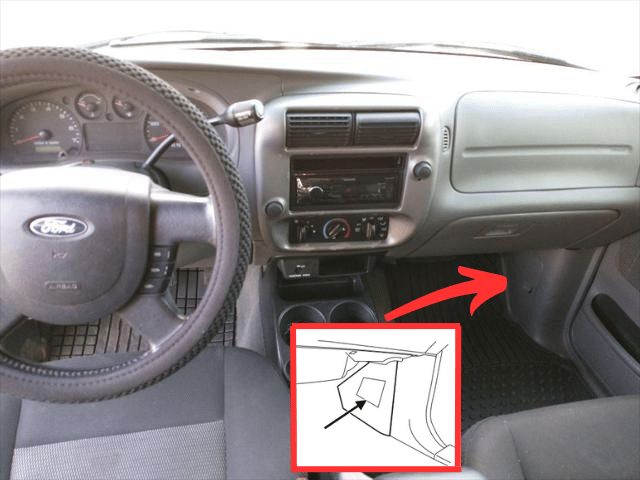
- Passenger Compartment : The fuse panel is located below and to the left of the steering wheel by the brake pedal behind the cover.
- Engine Compartment Fuse Box: The power distribution box is located in the engine compartment (left-side).
1. Passenger Compartment
2. Engine Compartment Fuse Box
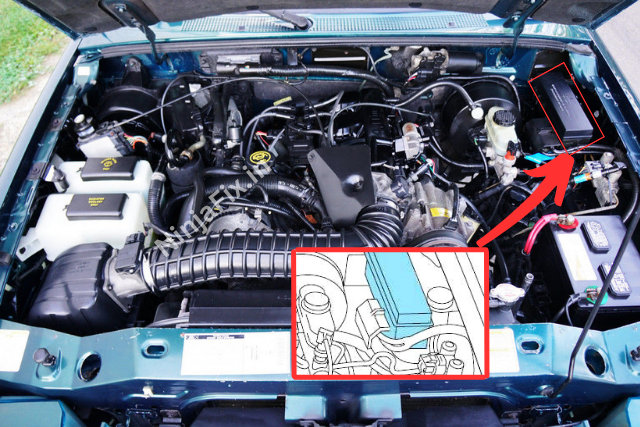
2005 Ford Ranger Fuse Box Diagram
Passenger Compartment
2005 Ford Ranger Interior Fuse Box Diagram
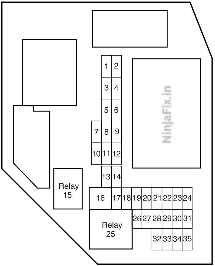
2005 Ford Ranger Interior Fuse Box Details
| No | Amps | Circuit Protected | Problem, if malfunction or blown |
|---|---|---|---|
| 1 | 5 | Instrument panel dimmer switch | |
| 2 | 10 | Trailer tow park lamps | |
| 3 | 10 | Right low beam headlamp | |
| 4 | 10 | Left low beam headlamp | |
| 5 | 30 | Windshield wipers/washer | |
| 6 | 10 | Radio (RUN/ACCY) | |
| 7 | 5 | Headlamp illumination indicator | |
| 8 | 10 | Restraints Control Module (RCM), PADI (Passenger Air bag Deactivation Indicator) | |
| 9 | 5 | Cluster air bag indicator | |
| 10 | 10 | Cluster (RUN/START), 4×4 module (RUN/START) | |
| 11 | 10 | Smart Junction Box (SJB) (Logic power) | |
| 12 | 15 | Center console subwoofer amplifier | |
| 13 | 15 | Horn, Interior lamps | |
| 14 | 15 | High beam headlamp, High beam indicator (cluster) | |
| 15 | — | One-touch down relay | |
| 16 | 30 | Power windows | |
| 17 | 15 | Turn signals/Hazards | |
| 18 | — | Not used | |
| 19 | 20 | Center High-Mounted Stop Lamp (CHMSL)/Stop lamps | |
| 20 | 10 | Anti-lock Brake System (ABS) module, Brake-shift interlock, Speed control module, Back-up lamps, Overdrive cancel switch, Electronic flasher (turn/hazard) | |
| 21 | 5 | Starter relay | Problem in starting. |
| 22 | 5 | Spare | |
| 23 | 30 | Headlamps (low and high beam) | |
| 24 | 20 | Radio | |
| 25 | — | Accessory relay | |
| 26 | 2 | Brake pressure switch | |
| 27 | 10 | Climate control blower relay/blend doors, 4×4 module | |
| 28 | 15 | 4×4 module B+ | |
| 29 | 20 | Cigar lighter or power point, Diagnostic connector (OBD II) | |
| 30 | 5 | Power mirrors | |
| 31 | 20 | Front park lamps, Rear park lamps, License plate lamps | |
| 32 | 5 | Brake switch (logic) | |
| 33 | 5 | Instrument cluster | |
| 34 | 20 | Power point | |
| 35 | 15 | Power locks |
2005 Ford Ranger fuse box diagram under hood
2.3 L Engine Ford Ranger Power Distribution Fuse Box Diagram
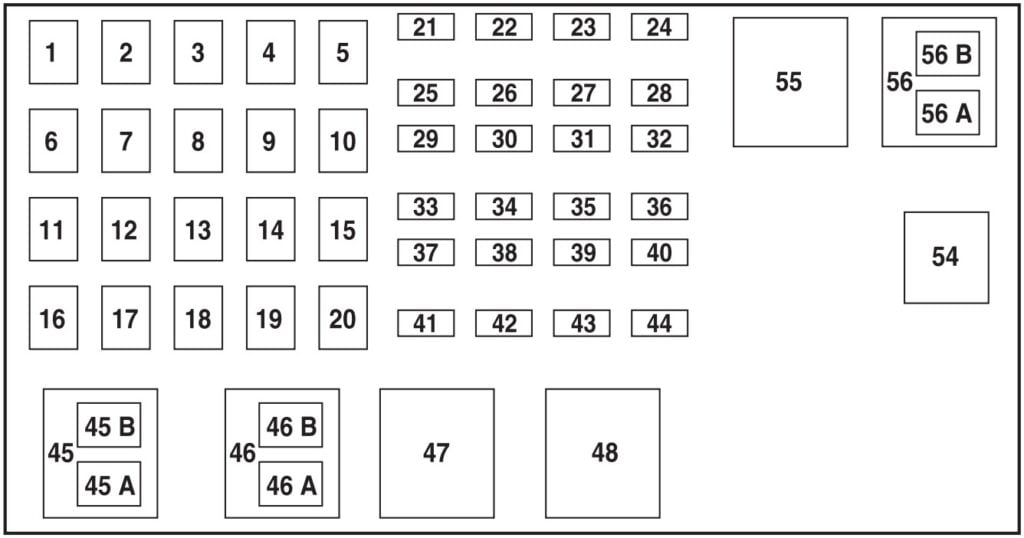
2005 Ford Ranger 2.3 Liter Under hood Fuse Box Details
| No | A | Circuit Protected | Problem, if blown or malfunctioned |
|---|---|---|---|
| 1 | 40 | Interior fuse panel (SJB) | |
| 2 | 40 | Amplifier (Tremor audio system only) | |
| 3 | 40 | Interior fuse panel (SJB) | |
| 4 | — | Not Used | |
| 5 | 50** | Interior fuse panel (SJB) | |
| 6 | — | Not Used | |
| 7 | 40* | Starter relay fuse | Problem in starting. |
| 8 | — | Not Used | |
| 9 | 40 | Ignition switch | |
| 10 | — | Not Used | |
| 11 | 30A** | Powertrain Control Module (PCM), Engine sensors | |
| 12 | — | Not Used | |
| 13 | 30** | Blower motor (climate control) | |
| 14 | — | Not Used | |
| 15 | Not Used | ||
| 16 | — | Not Used | |
| 17 | 40** | ABS (motor) | |
| 18 | — | Not Used | |
| 19 | 20** | Engine fan | |
| 20 | — | Not Used | |
| 21 | 10* | PCM | |
| 22 | — | Not Used | |
| 23 | 20* | Fuel Pump | Problem in starting. |
| 24 | — | Not Used | |
| 25 | 10* | A/C Clutch Solenoid | |
| 26 | — | Not Used | |
| 27 | — | Not Used | |
| 28 | Not Used | ||
| 29 | — | Not Used | |
| 30 | — | Not Used | |
| 31 | — | Not Used | |
| 32 | 30 | Anti-lock brake system (ABS) module | |
| 33 | — | Not Used | |
| 34 | — | Not Used | |
| 35 | — | Not Used | |
| 36 | — | Not Used | |
| 37 | — | Not Used | |
| 38 | 7,5* | Trailer tow (right turn) | |
| 39 | — | Not Used | |
| 40 | — | Not Used | |
| 41 | 15* | HEGOs | |
| 42 | 7,5* | Trailer tow (left turn) | |
| 43 | — | Not Used | |
| 44 | — | Not Used | |
| Relay | |||
| 45A | — | Wiper HI/LO relay | |
| 45B | — | Wiper Park/Run relay | |
| 46A | — | Fuel pump relay | Problem in starting. |
| 46B | — | Washer pump relay | |
| 47 | — | Engine fan relay | |
| 48 | — | Starter relay | Problem in starting. |
| 49 | — | Not Used | |
| 50 | — | Not Used | |
| 51 | — | Not Used | |
| 52 | — | Not Used | |
| 53 | — | Not Used | |
| 54 | — | PCM Relay | |
| 55 | — | Blower relay | |
| 56A | — | A/C clutch solenoid relay | |
| 56B | — | Not used | |
3.0 L & 4.0 L Engine Ford Ranger Power Distribution Fuse Box Diagram
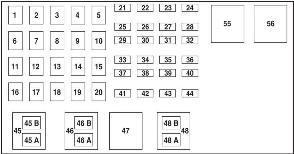
2005 Ford Ranger 3.0 L & 4.0 L Under hood Fuse Box Details
| No | Amps | Protected Circuit | Problem, if blown or malfunctioned |
|---|---|---|---|
| 1 | 40 | Interior fuse panel (SJB) | |
| 2 | 40** | Amplifier (Tremor audio system only) | |
| 3 | 50** | Interior fuse panel (SJB) | |
| 4 | — | Not Used | |
| 5 | 50** | Interior fuse panel (SJB) | |
| 6 | — | Not Used | |
| 7 | 40** | Starter relay fuse | Problem in starting. |
| 8 | — | Not used | |
| 9 | 40** | Ignition switch | |
| 10 | — | Not Used | |
| 11 | 30** | Powertrain Control Module (PCM) relay fuse | |
| 12 | — | Not used | |
| 13 | 30** | Blower motor (climate control) | |
| 14 | — | Not Used | |
| 15 | 30** | Anti-lock Brake System (ABS) (solenoids) | |
| 16 | — | Not Used | |
| 17 | 40** | ABS (motor) | |
| 18 | — | Not Used | |
| 19 | — | Not Used | |
| 20 | — | Not Used | |
| 21 | 10* | PCM | |
| 22 | — | Not Used | |
| 23 | 20* | Fuel Pump | Problem in starting. |
| 24 | — | Not Used | |
| 25 | 10* | A/C Clutch Solenoid | |
| 26 | — | Not Used | |
| 27 | 20* | 4×4 module | |
| 28 | — | Not Used | |
| 29 | — | Not Used | |
| 30 | — | Not Used | |
| 31 | 15* | Foglamps | |
| 32 | — | Not Used | |
| 33 | — | Not Used | |
| 34 | — | Not Used | |
| 35 | — | Not Used | |
| 36 | — | Not Used | |
| 37 | — | Not Used | |
| 38 | 7,5* | Trailer tow (right turn) | |
| 39 | — | Not Used | |
| 40 | — | Not Used | |
| 41 | 15* | HEGOs | |
| 42 | 7,5* | Trailer tow (left turn) | |
| 43 | — | Not Used | |
| 44 | — | Not Used | |
| Relay | |||
| 45A | — | Wiper HI/LO relay | |
| 45B | — | Wiper Park/Run relay | |
| 46A | — | A/C clutch solenoid | |
| 46B | — | Washer pump relay | |
| 47 | — | PCM relay | |
| 48A | — | Fuel pump relay | Problem in starting. |
| 48B | — | Fog lamp relay | |
| 51 | — | Not Used | |
| 52 | — | Not Used | |
| 53 | — | Not used | |
| 54 | — | Not used | |
| 55 | — | Blower relay | |
| 56 | — | Starter relay | Problem in starting. |
WARNING: The terminal and harness assignments for individual connectors may vary depending on the vehicle’s equipment level, model, and market. It is recommended to refer to the fuse box diagram provided at the back of the fuse box cover for accurate information.

