Where are the Fuse Boxes located in the 2016 GMC Sierra?
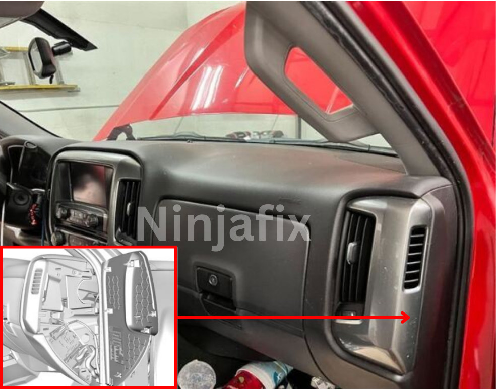
2016 GMC Sierra has 3 main boxes with fuses and relays. One is under the hood (Engine Compartment) and two are in the Passenger Compartment i.e. on the left(Driver’s side) and another on the right(Passenger’s Side) of the Instrument Panel or Dashboard.
2016 GMC Sierra Under Dash Fuse Box and Relay Location
The auxiliary fuse box (If equipped) is located next to the interior fuse box. To open the lid, pull the tab in the direction as shown in the illustration.
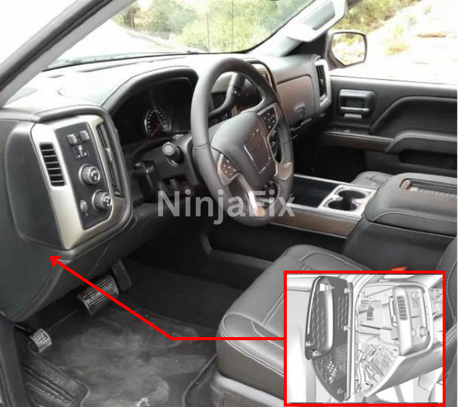
There are two fuse block on either side of the Dashboard and the access door is on the driver’s side edge of the instrument panel and Passenger’s side located in the same area. Pull off the covers on either side to access the fuse block.
2016 GMC Sierra Under Hood Fuse Box and Relay location
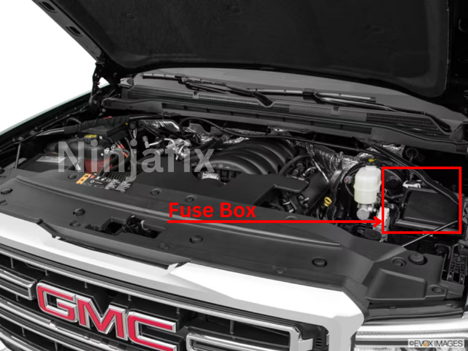
The under hood fuse block in the engine compartment on the driver’s side of the vehicle near the battery. Lift the cover for access to the fuse relay block.
2016 GMC Sierra under Dash Fuse Box Layout
2016 GMC Sierra Under Dash Fuse Box Diagram(Left)
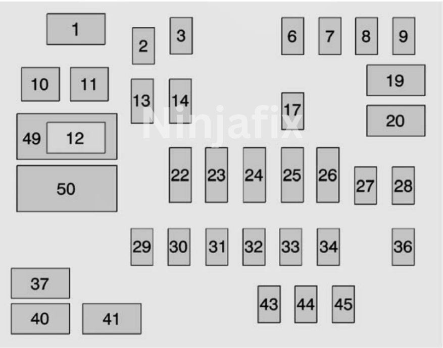
2016 GMC Sierra under Dash Fuse Box and Relay Details(Left)
Assignment of the fuses in the Passenger Compartment(Driver’s Side)
| No. | Usage |
| 1 | Accessory Power Outlet 2 |
| 2 | SEO Retained Accessory Power |
| 3 | Universal Garage Door Opener/lnside Rearview Mirror |
| 6 | Body Control Module 3 |
| 7 | Body Control Module 5 |
| 8 | Driver Window Switch/Mirror Switch |
| 9 | Spare |
| 10 | Accessory Power Outlet Retained Accessory Power |
| 11 | Accessory Power Outlet Battery |
| 12 | Accessory Power Outlet 1/Cigarette Lighter |
| 13 | Discrete Logic Ignition Switch |
| 14 | Switch Backlighting |
| 17 | Body Control Module 1 |
| 19 | Spare |
| 20 | Spare |
| 22 | Heater, Ventilation, and Air Conditioning/Auxiliary Heater, Ventilation and Air Conditioning Ignition |
| 23 | Instrument Cluster Ignition/Sensing Diagnostic Module Ignition |
| 24 | Spare |
| 25 | Data Link Connector/Driver Seat Module |
| 26 | Passive Entry Passive Start/Heater, Ventilation, and Air Conditioning |
| 27 | Spare |
| 28 | Spare |
| 29 | Park Enable/Electrically Adjustable Pedals |
| 30 | SEO |
| 31 | Accessory/Run Crank |
| 32 | Heated Steering Wheel |
| 33 | Spare |
| 34 | Instrument Cluster |
| 36 | Spare |
| 37 | Spare |
| 40 | Left Doors |
| 41 | Driver Power Seat |
| 43 | Left Front Heated/Cooled Seat |
| 44 | Right Front Heated/Cooled Seats |
| 45 | Spare |
| 49 | Retained Accessory Power/Accessory |
| 50 | Run/Crank |
2016 GMC Sierra Under Dash Fuse Box Diagram(Right)
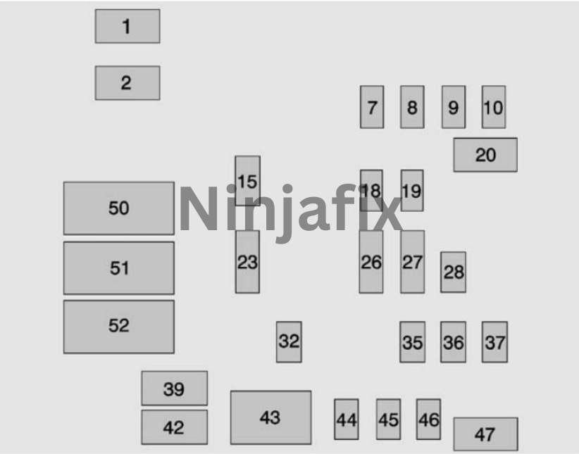
2016 GMC Sierra under Dash Fuse Box and Relay Details(Right)
Assignment of the fuses in the Passenger Compartment(Passenger’s Side)
| No. | Usage |
| 1 | Accessory Power Outlet 3 |
| 2 | Accessory Power Outlet 4 |
| 7 | Body Control Module 4 |
| 8 | Body Control Module 8 |
| 9 | Rear Seat Entertainment |
| 10 | Cargo Lamp |
| 15 | Steering Wheel Controls |
| 18 | Radio |
| 19 | Spare |
| 20 | Sunroof |
| 23 | Airbag/lnfo |
| 26 | Export/Power Take Off/SEO Battery 1 |
| 27 | Obstacle Detection/USB Ports |
| 28 | Body Control Module 2 |
| 32 | SEO Battery 2 |
| 35 | AC Inverter |
| 36 | Amplifier |
| 37 | Spare |
| 39 | Rear Sliding Window |
| 42 | Right Door Window Motor |
| 43 | Front Blower |
| 44 | SEO |
| 45 | Body Control Module 6 |
| 46 | Body Control Module 7 |
| 47 | Passenger Seat |
| 50 | Retained Accessory Power/Accessory |
| 51 | Rear Sliding Window Open |
| 52 | Rear Sliding Window Close |
2016 GMC Sierra Under Hood Fuse Box Layout
2016 GMC Sierra Under Hood Fuse Box Diagram
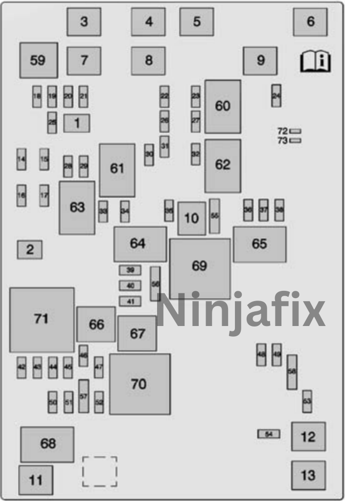
2016 GMC Sierra under Hood Fuse Box and Relay Details
Assignment of the fuses in the Engine Compartment
| No. | Usage |
| Micro J-Case Fuses | |
| 1 | Trailer Brake |
| 2 | Trailer Battery |
| J-Case Fuses | |
| 3 | Antilock Brake System Pump |
| 4 | Instrument Panel BEC 1 |
| 5 | Spare |
| 6 | 4WD Tree |
| 7 | Spare |
| 8 | Instrument Panel BEC 2 |
| 9 | Spare |
| 10 | Rear Window Defogger |
| 11 | Starter |
| 12 | Cooling Fan 1 |
| 13 | Cooling Fan 2 |
| Mini Fuses (2 Pin) | |
| 14 | Trailer Stop/Turn Lamps, Left |
| 15 | Trailer Parking Lamps |
| 16 | Trailer Back-up Lamp |
| 17 | Trailer Stopfium Lamps, Right |
| Micro Fuses (2 Pin) | |
| 18 | Fuel Pump |
| 19 | Integrated Chassis Control Module |
| 20 | Electronic Suspension Control Module |
| 21 | Fuel Pump Power Module |
| 22 | Upfitter Switch 1 |
| 23 | Upfffler2 |
| 24 | Front Wiper |
| 25 | Antilock Brake System Valves |
| 26 | Upfitter SW 2 |
| 27 | Upfitter SW 3 |
| 28 | Parlang Lamps, Right |
| 29 | Parlang Lamps, Left |
| 30 | Upfitter 3 |
| 31 | Upfitter SW 4 |
| 32 | Upfitter 4 |
| 33 | Back-up Lamps |
| 34 | Engine Control Module Ignition |
| 35 | Air Conditioning Compressor Clutch |
| 36 | Heated Mirrors |
| 37 | Upfflter 1 |
| 38 | Center High-Mounted Stoplamp |
| 39 | Miscellaneous Ignition |
| 40 | Transmission Ignition |
| 41 | Fuel Pump 2 |
| 42 | Cooling Fan Clutch |
| 43 | Engine |
| 44 | Fuel Injectors A, Odd |
| 45 | Fuel Injectors B, Even |
| 46 | Oxygen Sensor B |
| 47 | Throttle Control |
| 48 | Horn |
| 49 | Fog Lamp |
| 50 | Oxygen Sensor A |
| 51 | Engine Control Module |
| 52 | Interior Heater |
| 53 | Spare |
| 54 | Aeroshutter |
| 55 | Front Washer |
| Micro Fuses (3 Pin) | |
| 56 | Air Conditioning Compressor/Battery Regulated Voltage Control |
| 57 | Air Conditioning CompressorModule/Battery Pack |
| 58 | Transmission Control Module/Engine Control Module |
| 59 | Headlamps |
| Micro Relays | |
| 60 | Fuel Pump |
| 61 | Upfitter2 |
| 62 | Upfitter3 |
| 63 | Upfitter4 |
| 64 | Trailer Parking Lamps |
| 65 | Run/Crank |
| 66 | Upfitter 1 |
| 67 | Fuel Pump 2 |
| 68 | Air Conditioning Control |
| 69 | Starter |
| 70 | Rear Window Defogger |
| 71 | Engine Control Module |
| Solid State Relay | |
| 72 | Cooling Fan Clutch |
WARNING: The terminal and harness assignments for individual connectors may vary depending on the vehicle’s equipment level, model, and market. It is recommended to refer to the fuse box diagram provided at the back of the fuse box cover for accurate information.

