Where are the Fuse Boxes located in 2013 Honda Accord?
2013 Honda Accord has 2 main boxes with fuses and relays. One in the cabin(Passenger Compartment), another under the hood(Engine Compartment) located near battery.
Learn more about the Fuse Box Diagram of Honda Accord for other year models.
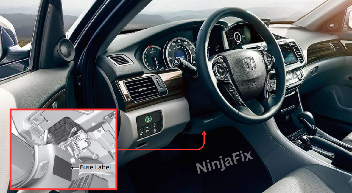
2013 Honda Accord Under Dash Fuse Box and Relay Location
The Fuse and Relay box is positioned under the dashboard, on the right side of the steering column.
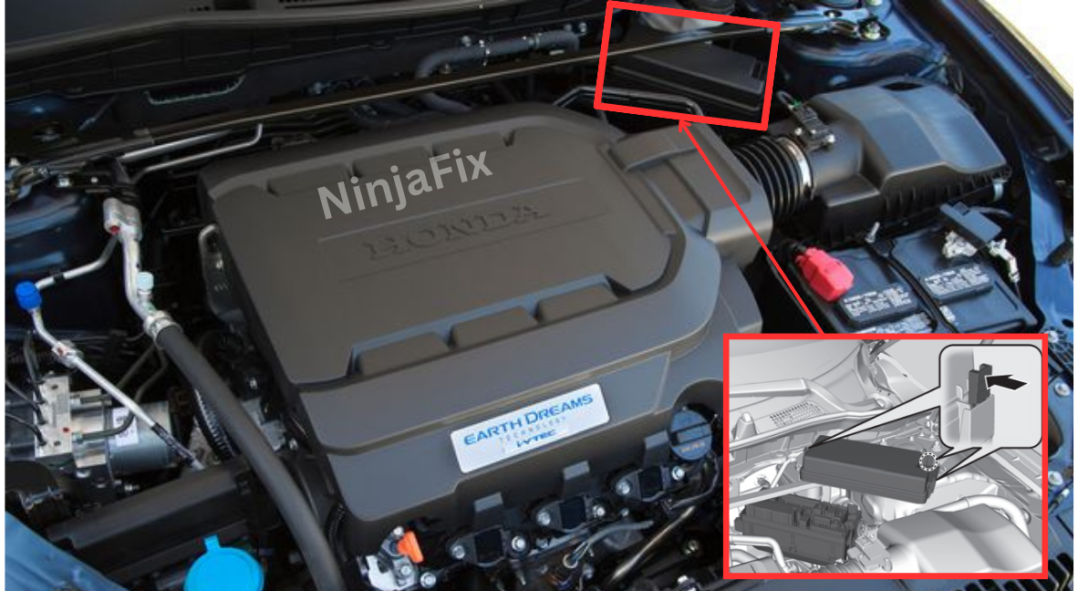
2013 Honda Accord Under Hood Fuse and Relay box location
The under hood fuse box is situated in the engine compartment, close to the brake fluid reservoir.
2013 Honda Accord Under Dash Fuse Box Layout
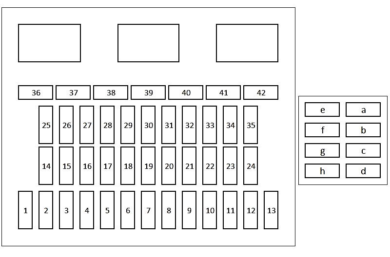
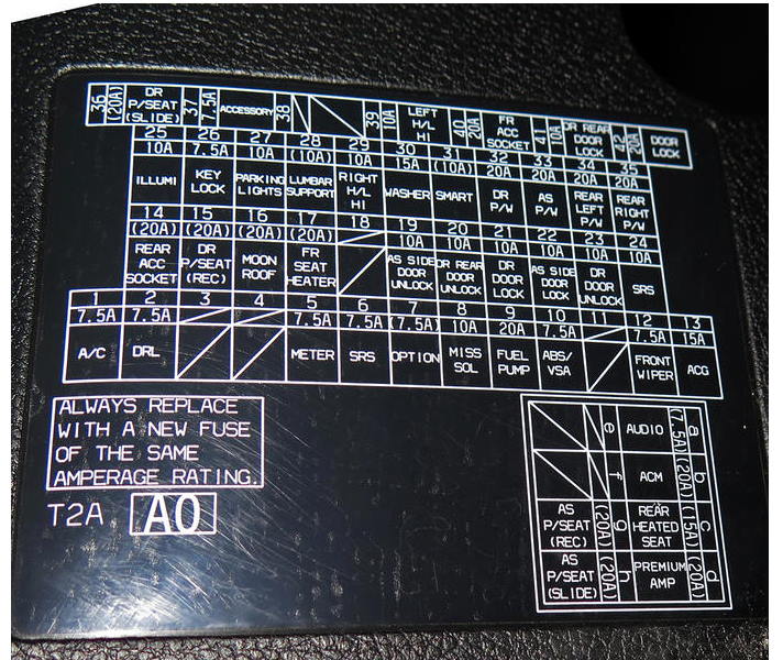
2013 Honda Accord Under Dash Fuse and relay Box Details
| № | Circuit Protected | Amps |
|---|---|---|
| 1 | A/C | 7.5 A |
| 2 | DRL | 7.5 A |
| 3 | — | — |
| 4 | – | – |
| 5 | Meter | 7.5 A |
| 6 | SRS | 7.5 A |
| 7 | Option | (7.5 A) |
| 8 | MISS SOL | 10 A |
| 9 | Fuel Pump | 20 A |
| 10 | ABS/VSA | 7.5 A |
| 11 | — | — |
| 12 | Front Wiper | 7.5 A |
| 13 | ACG | 15 A |
| 14 | Rear Accessory Power Socket (Console Compartment) | (20 A) |
| 15 | Driver’s Power Seat Reclining (option) | (20 A) |
| 16 | Moonroof (option) | (20 A) |
| 17 | Front Seat Heaters (option) | (20 A) |
| 18 | – | – |
| 19 | Passenger Side Door Unlock | 10 A |
| 20 | Driver Side Rear Door Unlock | 10 A |
| 21 | Driver’s Door Lock | 10 A |
| 22 | Passenger Side Door Lock | 10 A |
| 23 | Driver’s Door Unlock | 10 A |
| 24 | SRS | 10 A |
| 25 | Illumination | 10 A |
| 26 | Key Lock | 7.5 A |
| 27 | Parking Lights | 10 A |
| 28 | Lumbar Support (option) | (10 A) |
| 29 | Right Headlight High Beam | 10 A |
| 30 | Washer | 15 A |
| 31 | SMART (option) | (10 A) |
| 32 | Driver’s Power Window | 20 A |
| 33 | Front Passenger’s Power Window | 20 A |
| 34 | Rear Driver Side Power Window | 20 A |
| 35 | Rear Passenger Side Power Window | 20 A |
| 36 | Driver’s Power Seat Sliding (option) | (20 A) |
| 37 | ACCESSORY | 7.5 A |
| 38 | — | — |
| 39 | Left Headlight High Beam | 10 A |
| 40 | Accessory Power Socket (Console Panel) | 20 A |
| 41 | Driver Side Rear Door Lock | 10 A |
| 42 | Door Lock | 20 A |
| a | Audio (option) | (7.5 A) |
| b | ACM (option) | (20 A) |
| c | Rear Seat Heaters (option) | (15 A) |
| d | Premium Amp (option) | (20 A) |
| e | — | — |
| f | — | — |
| g | Passenger’s Power Seat Reclining (option) | (20 A) |
| h | Passenger’s Power Seat Sliding (option) | (20 A) |
2013 Honda Accord Under Hood Fuse Box Layout
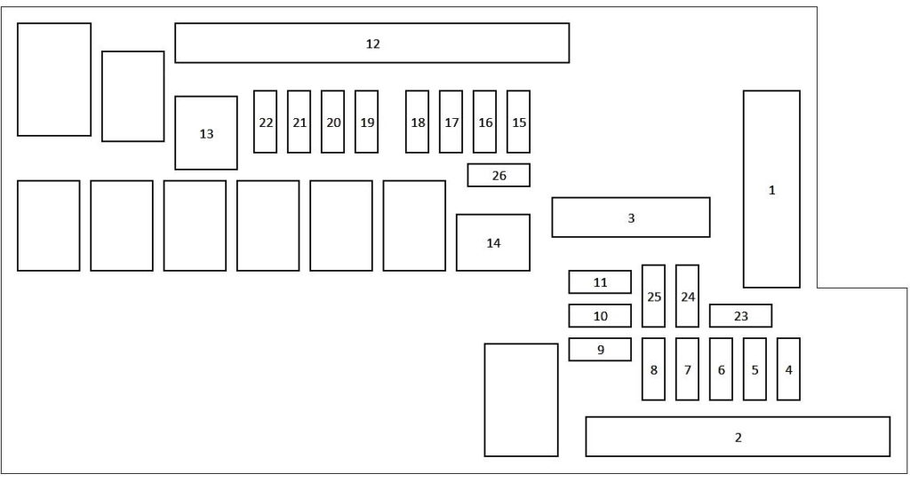
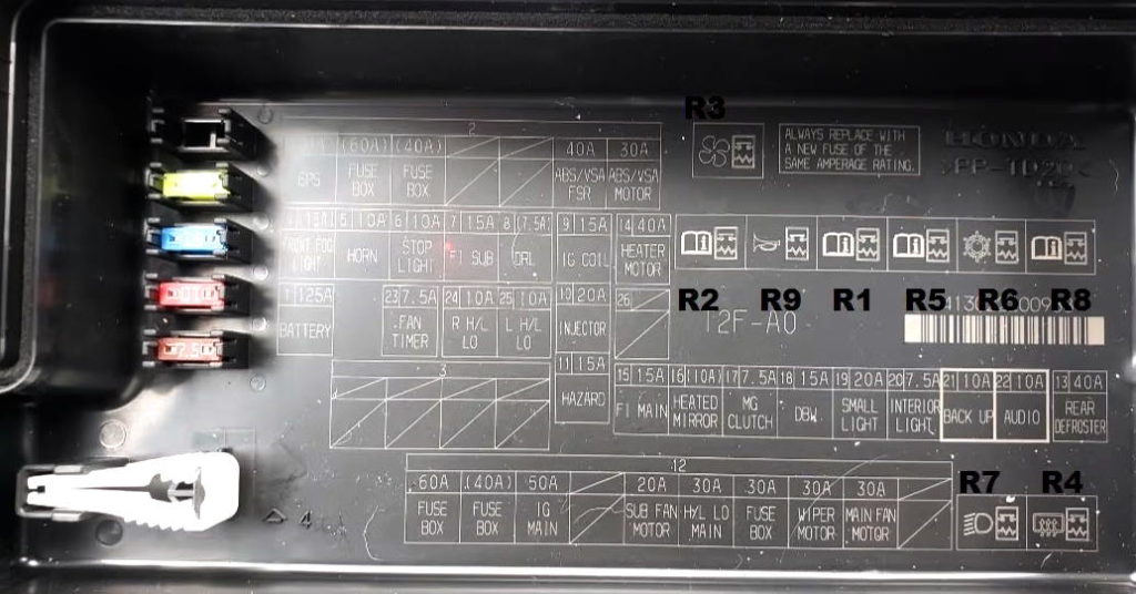
Relay designation
- R1 – MAIN RELAY 1
- R2 – IGNITION COIL RELAY
- R3 – FAN MOTOR RELAY
- R4 – RELAY FOR REAR HEATER
- R5 – ETCS CONTROL RELAY
- R6 – A/C COMPRESSOR CLUTCH RELAY
- R7 – LOW BEAM RELAY
- R8 – SUB REL PGM-FI
- R9 – HORN RELAY
2013 Honda Accord Under Hood Fuse Box Details
| № | Circuit Protected | Amps |
|---|---|---|
| 1 | Battery | 125 A |
| 2 | EPS | 70 A |
| 2 | Fuse Box Main 1 | (60 A) |
| 2 | Fuse Box Option 1 | (40 A) |
| 2 | – | – |
| 2 | – | – |
| 2 | ABS/VSA FSR | 40 A |
| 2 | ABS/VSA Motor | 30 A |
| 3 | – | – |
| 3 | – | – |
| 3 | – | – |
| 3 | – | – |
| 4 | Front Fog Light (Models with the smart entry system have an ENGINE START/STOP button instead of an ignition switch) | (15 A) |
| 5 | Horn | 10 A |
| 6 | Stop Light | 10 A |
| 7 | FI Sub | 15 A |
| 8 | DRL | (7.5 A) |
| 9 | IG Coil | 15 A |
| 10 | Injector (4-cyl) | 20 A |
| 11 | Hazard | 15 A |
| 12 | Fuse Box Main 2 | 60 A |
| 12 | Fuse Box Option 2 | (40 A) |
| 12 | IG Main 1 | 50 A / 30 A (Models with smart entry system) |
| 12 | IG Main 2 (Models with smart entry system) | 30 A |
| 12 | Sub Fan Motor | 20 A (4-cyl) / 30 A (6-cyl) |
| 12 | Headlight Low Beam Main | 30 A |
| 12 | Fuse Box | 30 A |
| 12 | Wiper Motor | 30 A |
| 12 | Main Fan Motor | 30 A |
| 12 | Starter Motor (Models with smart entry system) | 30 A |
| 13 | Rear Defogger | 40 A |
| 14 | Heater Motor | 40 A |
| 15 | FI Main | 15 A |
| 16 | Heated Door Mirror (Models with the smart entry system have an ENGINE START/STOP button instead of an ignition switch) | (10 A) |
| 17 | MG Clutch | 7.5 A |
| 18 | DBW | 15 A |
| 19 | Small Light | 20 A |
| 20 | Interior Light | 7.5 A |
| 21 | Back Up | 10 A |
| 22 | Audio | 10 A |
| 23 | Fan Timer | 7.5 A |
| 24 | Right Headlight Low Beam | 10 A |
| 25 | Left Headlight Low Beam | 10 A |
| 26 | – | – |
WARNING: The terminal and harness assignments for individual connectors may vary depending on the vehicle’s equipment level, model, and market. It is recommended to refer to the fuse box diagram provided at the back of the fuse box cover for accurate information.
