Where are the Fuse Boxes located in the 2023 Honda Civic?
In 2023 Honda Civic has two main boxes and one sub fuse box with fuses and relays. One main fuse box and sub fuse box located in the cabin (Passenger Compartment) and another is under the hood (Engine Compartment).
2023 Honda Civic Under Dash Fuse Box and Relay Location
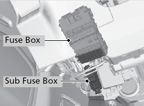
The interior fuse box is located under the dashboard on the driver’s side. The fuse label is attached under the steering column.
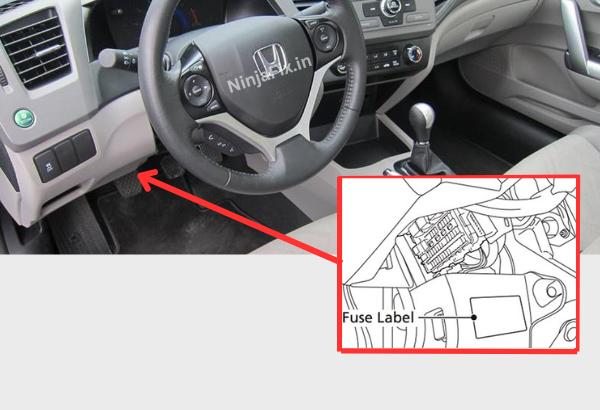
The auxiliary fuse box (If equipped) is located next to the interior fuse box. To open the lid, pull the tab in the direction as shown in the illustration.
The sub fuse box (If equipped) is located next to the interior fuse box. To open the lid, pull the tab in the direction as shown in the illustration.
2023 Honda Civic Under Hood Fuse Box and Relay location
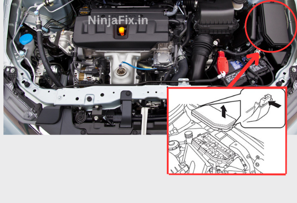
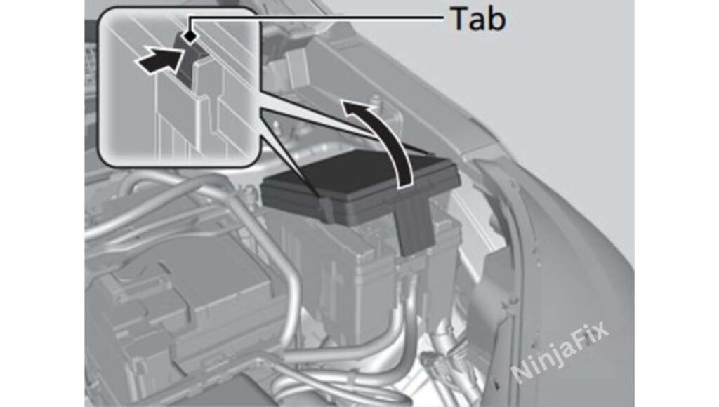
The Engine compartment fuse block is in the engine compartment is located on the driver side of the vehicle near the brake fluid reservoir.
2023 Honda Civic under Dash Fuse Box Layout
2023 Honda Civic Under Dash Fuse Box Diagram
The block fuse box diagram of under dash fuse box for the 2023 Honda Civic is usually located at the backside or inner cover of the fuse box. This diagram serves as a reference, detailing the specific fuses and relays, along with their respective amperage ratings and the systems they protect or control within the vehicle. It’s a helpful guide for identifying and replacing fuses when necessary.
2023 Honda Civic under Dash Fuse Box and Relay Details
Assignment of the fuses in the Passenger Compartment
| SN | Circuit Protected | Amps |
| 1 | P/W DR | 20 A |
| 2 | P/W AS | 20 A |
| 3 | P/W RR R | 20 A |
| 4 | P/W RR L | 20 A |
| 5 | OPTION | 10 A |
| 6 | SRS | 10 A |
| 7 | T/G MTR / TRUNK ACT | 10 A |
| 8 | – | – |
| 9 | FR ACC SOCKET | 20 A |
| 10 | DOOR LOCK | 20 A |
| 11 | METER | 10 A |
| 12 | OPTION3 (ST CUT) | 10 A |
| 13 | OPTION2 (RR WIP)* | (10 A) |
| 14 | OPTION6 (VB SOL) | 10 A |
| 15 | DR DOOR UNLOCK | (10 A) |
| 16 | SUNROOF* | (20 A) |
| 17 | SBW1* | (10 A) |
| 18 | – | – |
| 19 | – | – |
| 20 | RR FOG* | (10 A) |
| 21 | CARGO ACC SOCKET* | (20 A) |
| 22 | SMART | 10 A |
| 23 | DR DOOR LOCK | (10 A) |
| 24 | SBW2* | (7.5 A) |
| 25 | IMG | 10 A |
| 26 | SRS | 10 A |
| 27 | ACG / D/V / ST CUT RLY | 20 A |
| 28 | OPTION5 | 10 A |
| 29 | FUEL PUMP | 15 A |
| 30 | L SIDE DOOR UNLOCK | 10 A |
| 31 | R SIDE DOOR UNLOCK | 10 A |
| 32 | – | – |
| 33 | – | – |
| 34 | – | – |
| 35 | – | – |
| 36 | OPTION3 (SUNSHADE)* | (20 A) |
| 37 | IGA2* | (15 A) |
| 38 | – | – |
| 39 | R SIDE DOOR LOCK | 10 A |
| 40 | P/SEAT REC / RR HI* | (20 A) |
| 41 | P/SEAT SLIDE / FR HI* | (20 A) |
| 42 | – | – |
| 43 | A/C | 10 A |
| 44 | DRL | 10 A |
| 45 | ACC | 10 A |
| 46 | ACC KEY LOCK | 10 A |
| 47 | L SIDE DOOR LOCK | 10 A |
| 48 | H/SEAT | 20 A |
| 49 | AS P/SEAT REC* | (20 A) |
| 50 | P/LUMBAR DR* | (10 A) |
| 51 | P/LUMBAR AS* | (10 A) |
| 52 | RR H/SEAT* | (20 A) |
| 53 | AS P/SEAT SLI* | (20 A) |
| 54 | OPTION1 / FUEL LID | 10 A |
| 55 | AUDIO AMP* | (30 A) |
| 56 | ADS* | (30 A) |
Sub Fuse Box
| SN | Circuit Protected | Amps |
| A | BACKUP2 MAIN | (10 A) |
| B | AUDIO SUB VST* | (7.5 A) |
| C | ACC VST | (10 A) |
| D | VST 1 | (10 A) |
| E | AUDIO VST | (15 A) |
| F | EOP* | (20 A) |
| G | – | – |
| H | VST 2 | (10 A) |
2023 Honda Civic Under Hood Fuse Box Layout
2023 Honda Civic Under Hood Fuse Box Diagram
The block fuse box diagram of under hood fuse box for the 2023 Honda Civic is usually located at the backside or inner cover of the fuse box. This diagram serves as a reference, detailing the specific fuses and relays, along with their respective amperage ratings and the systems they protect or control within the vehicle. It’s a helpful guide for identifying and replacing fuses when necessary.
2023 Honda Civic under Hood Fuse Box and Relay Details
Assignment of the fuses in the Engine compartment
| SN | Circuit Protected | Amps |
| 1 | BATTERY | 125 A |
| 2 | – | 40 A |
| – | 40 A | |
| F/BOX OPTION | 60 A | |
| – | 40 A | |
| F/BOX OPTION2 | 40 A | |
| DC/DC2 | (30 A) | |
| F/BOX MAIN | 60 A | |
| 3 | – | 40 A |
| – | 40 A | |
| – | 40 A | |
| RR DEFROSTER | 40 A | |
| – | 40 A | |
| HTR MTR | 40 A | |
| – | 40 A | |
| 4 | – | 30 A |
| ABS/VSA MTR | 40 A | |
| DC/DC | (30 A) | |
| – | 30 A | |
| IG MAIN | 30 A | |
| – | 30 A | |
| R/M2 | 30 A | |
| 5 | ST MAGNETIC SW | 30 A |
| WIPER | 30 A | |
| EPS | 70 A | |
| R/M1 | 30 A | |
| ABS/VSA FSR | 40 A | |
| MAIN FAN | 30 A | |
| F/BOX MAIN2 | 40 A | |
| 6 | SUB FAN | 30 A |
| 7 | IG MAIN2 | 30 A |
| 8 | – | – |
| 9 | EVP* | (30 A) |
| 10 | AUDIO SUB* | (7.5 A) |
| 11 | – | – |
| 12 | – | – |
| 13 | H/STRG* | (10 A) |
| 14 | – | – |
| 15 | FR FOG* | (10 A) |
| 16 | MG CLUTCH | 10 A |
| 17 | WASHER | 15 A |
| 18 | HORN | 10 A |
| 19 | BACK UP | 15 A |
| 20 | AUDIO* | (15 A) |
| 21 | – | – |
| 22 | DBW | 15 A |
| 23 | EOP* | (20 A) |
| 24 | BACKUP FI-ECU | 10 A |
| 25 | IGP | 15 A |
| 26 | TCU* | (15 A) |
| 27 | LCM L | (15 A) |
| 28 | INJ* | (15 A) |
| 29 | STOP | 10 A |
| 30 | LCM R | (15 A) |
| 31 | IG COIL | 15 A |
| 32 | – | – |
| 33 | HAZARD | 15 A |
| 34 | AUDIO SUB VST* | (7.5 A) |
| 35 | – | – |
| 36 | AUDIO VST MAIN | (30 A) |
| 37 | BACKUP2 | (30 A) |
| 38 | – | – |
| 39 | – | – |
| 40 | VBACT* | (10 A) |
| 41 | IGPS [LAF] | 10 A |
| 42 | IG1 MON2 | 7.5 A |
WARNING: The terminal and harness assignments for individual connectors may vary depending on the vehicle’s equipment level, model, and market. It is recommended to refer to the fuse box diagram provided at the back of the fuse box cover for accurate information.

