Relays are indispensable electrical components utilized in various applications, including automobiles, motorcycles, home automation systems, and household appliances.
Their primary purpose is to enable a low-power logic signal to control a much higher-power circuit. Being able to effectively test a relay is essential for diagnosing a wide range of electrical issues in these systems.
How Do You Test a Relay ?
Testing a relay can be done using several methods, and the choice of method often depends on the tools and equipment available. In general practice, a relay can be tested using the following methods:
- Test a relay with swap Method (without a multimeter).
- Test a relay with test light.
- Test a relay with Multimeter.
Remember that safety is crucial when working with electrical components. Ensure that the power source is disconnected and follow safety precautions to prevent accidents or damage to the relay and other components.
How a Relay Works ?
Relays are essentially electrical switches controlled by a low-amperage current to enable the switching of high-amperage contacts. In an electromechanical relay, the low-amperage circuit powers an electromagnetic coil, which in turn operates the high-current contacts.
To test a relay, it is essential to identify the control circuit and load circuit. The configuration of the control circuit and load circuit varies based on the type of relay being used.
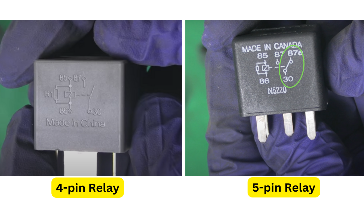
To identify the control circuit and load circuit, look for the diagram on the relay body. The terminal with a spring and a resistor in parallel is the control circuit, and the terminal with an open contactor is the load circuit.

In a 5-pin relay, pins 85 and 86 are generally for the control circuit to power the coil, while pins 30, 87, and 87a are for the load circuit. Pin 87a is the normally closed contact, and pin 87 is the normally open contact, with the load circuit switching between them depending on the relay’s state (pick-up or non-pick-up).

Why Relays Fail?
There are mainly three reasons due to which a relay may fail-
- Spring Fatigue: The relay spring, responsible for opening and closing contacts, can lose its elasticity over time, leading to the contacts getting stuck in a closed position.
- Coil Burnout: Overloading or electrical surges can cause the relay coil to burn out, preventing it from generating the necessary electromagnetic force to close the contacts.
- Poor Contact Alignment: Inaccurate alignment of relay contacts or improper contact pressure can result in unreliable connections, affecting the relay’s ability to function correctly.
Relay Test With Swap Method (Without Multimeter)
Swapping relays is indeed one of the easiest and most popular methods for testing a relay, especially when you to test a relay without a multimeter. It’s a practical way to quickly determine if the relay is the source of the problem.
How To Test a Relay With Swap Method ?
Here’s how it works in a nutshell:
Step 1:
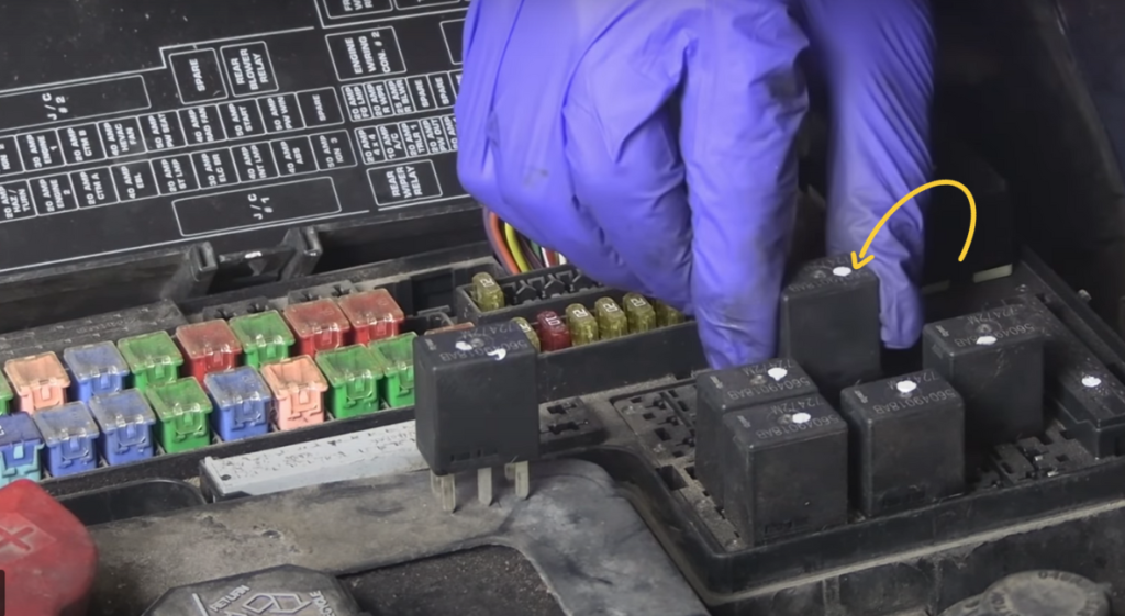
Locate the Suspected Relay: Find the relay you suspect to be faulty. It’s usually situated in a relay box, fuse box, or a specific compartment in your vehicle, depending on the make and model.

Step 2:
Remove the Relay: Carefully grip the relay and pull it straight out from its socket. Relays are usually designed to be plugged in, so you can easily remove them by hand.

Step 3:
Identify a similar relay: Look for another relay in your car or system that has the same rating and is responsible for controlling a non-essential system. For example, if you suspect a fuel pump relay is bad, you might swap it with a relay used for a non-critical function like windshield wipers.

Step 4:
Swap relay position: Gently push the similar relay into the empty socket that previously held the suspected faulty relay.
Step 5:
Test the Functionality: With the relay swapped, attempt to start or activate the system that was previously experiencing issues. If the problem is resolved, and the system now functions correctly, it’s a strong indicator that the suspected relay was indeed faulty.
Test a Relay With a Multimeter ?
Using a multimeter allows for detailed testing of both 4-pin and 5-pin relays. It’s a versatile tool for checking the resistance across the control and load circuits of the relay, helping you diagnose potential issues with the relay’s functionality. Whether you’re dealing with a 4-pin relay commonly used for simpler applications or a 5-pin relay with additional functionality, a multimeter can provide valuable insights into the relay’s condition.
How To Test a 4 or 5 Pin Relay With a Multimeter ?
If you suspect a faulty relay and want to perform a more detailed test using a multimeter, follow these steps:
Step 1:
Examine the relay closely to identify its pins. Most relays have a diagram on the casing indicating the pin functions. Generally, you’ll have:
- Control Circuit Pins (typically labeled 85 and 86).
- Normally Open (NO) Load Circuit Pin (usually 30)
- Normally Closed (NC) Load Circuit Pin (applicable for 5 pin)
Step 2: Set Up the Multimeter and Measure Resistance of coil
- Turn your multimeter on and select the resistance (ohms) setting.
- For this test, you’re checking the resistance across the control circuit pins (85 and 86).
- Place the multimeter’s probes on the control circuit pins. It doesn’t matter which probe goes to which pin because resistance is not polarity-sensitive.
- The multimeter will display the resistance value. A functioning relay typically has a low resistance (usually around 50-200 ohms) between its control circuit pins.

If the resistance is extremely high (indicating an open circuit) or very low (close to zero ohms, suggesting a short circuit), the relay may be faulty.
Step 3: Test the Load Circuit
If you suspect issues with the load circuit, you can also test the resistance between the load circuit pins.
- The resistance across these pins should be very high when the relay is inactive (in its “normally open” state) and very low when the relay is energized (in its “closed” state).
Test for Normally Open (NO) Circuit
- In both 4-pin and 5-pin relay, pins 30 and 87 are used for the “NO” load circuit
- In the normally open state (relay inactive), there should be little to no continuity, indicating a very high resistance or an open circuit. This is the expected result when the relay is off.

Test for Normally Closed (NC) Circuit
- In a 4-pin relay, there is no dedicated normally closed (NC) circuit. These relays typically only have a normally open (NO) circuit. In a 5-pin relay pins 30 and pin 87a is used for the normally closed (NC) load circuit
- In the normally closed state (relay inactive), there should be continuity, indicating a very low resistance, almost zero ohms. This means that the relay’s NC contacts are conducting when the relay is off.
Test for Normally Open (NO) Circuit in Pick-up Condition
Testing the normally open (NO) contacts of a relay by applying a 12V voltage across the control circuit pin is a good way to verify if the relay is functioning correctly.
- Apply 12V Voltage: Connect one end of a wire to the positive terminal of the 12V power source to the pin in the control circuit (either pin 85 or 86) of the relay.
- Check for NO Contacts: Using a multimeter, set it to the resistance (ohms) or continuity test mode. Check the the load circuit (across pin 30 & 87) that corresponds to the normally open (NO) contacts for both 4-pin relay and 5-pin relay.

Conclusion:
Understanding the relay’s control and load circuits, as well as the specific pin configurations for 4-pin and 5-pin relays, is fundamental for effective testing. Identifying potential failure reasons, such as worn-out springs, burnt coils, or poor contact alignment, helps diagnose relay issues accurately.