Where are the Fuse Boxes located in the 2007 Jeep Grand Cherokee?
2007 Jeep Grand Cherokee has 2 main boxes with fuses and relays. One is in the cabin (Passenger Compartment) and another is under the hood (Engine Compartment).
2007 Jeep Grand Cherokee Under Dash Fuse Box and Relay Location
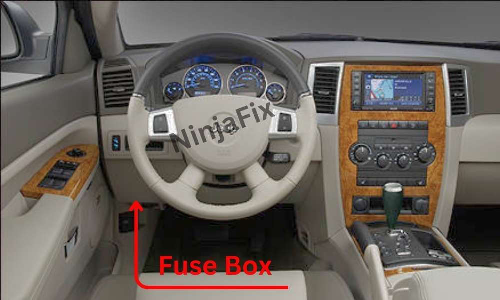
The Fuse and Relay box is located under the instrument panel (on the driver’s side), under the cover and is covered with trim.
2007 Jeep Grand Cherokee Under Hood Fuse Box and Relay location
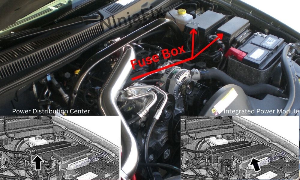
This power center houses plug-in “Cartridge” fuses, ISO relays, and Mini (Micro) fuses. A label inside the latching cover of the center identifies each component for ease of replacement, if necessary. Cartridge and mini (micro) fuses can be obtained from your authorized dealer.
2007 Jeep Grand Cherokee under Dash Fuse Box Layout
2007 Jeep Grand Cherokee under Dash Fuse Box and Relay Diagram
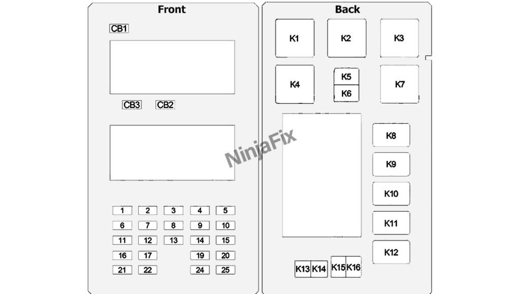
2007 Jeep Grand Cherokee under Dash Fuse Box and Relay Details
Assignment of the fuses and relays in the Passenger compartment
| Cavity | Amp/Color | Description |
|---|---|---|
| 1 | 30 Amp Green | Audio Amp (B+) |
| 2 | 15 Amp Blue | Sunroof (B+) |
| 3 | 10 Amp Red | Htd Mirror (EBL) |
| 4 | 20 Amp Yellow | Rr Pwr Out (B+) |
| 5 | 10 Amp Red | Rr HVAC (R/O) (XK Only) |
| 6 | Spare (B+) | |
| 7 | 20 Amp Yellow | Door Locks (B+) |
| 8 | 15 Amp Blue | Steer Col Lock (B+) (ELV) |
| 9 | 20 Amp Yellow | Pwr Outlet (B+) |
| 10 | 10 Amp Red | Final Drive Control Module (FDCM), Heater Ventilation, Air Conditioning (HVAC), Switch Bank, Transfer Case Switch, O/H, Heater Ventilation, Air Conditioning (HVAC) Relay, Rear Park Assist |
| 11 | Spare (B+) | |
| 12 | 10 Amp Red | Door Mods, Mem. Sw, O/H Lamps, IP Courtesy Lamps, Glove Box Lamp (B+) |
| 13 | 10 Amp Red | Autowipe (R/A) |
| 14 | 20 Amp Yellow | Cigar Ltr (R/A) |
| 15 | 10 Amp Red | Tire Pressure Transducers (R/O) |
| 16 | 10 Amp Red | Steering Control Module (SCM), Diag. Connector, Cluster (B+) |
| 17 | 15 Amp Blue | Flipper Glass (B+) |
| 19 | Spare (R/S) | |
| 20 | 10 Amp Red | Sentry Key Remote Entry Module (SKREEM), Cluster (R/S) |
| 21 | Spare (Acc Delay) | |
| 22 | 15 Amp Blue | Rear Wiper (B+) |
| 24 | 10 Amp Red | Power Distribution Center (PDC) Relays, Final Drive Control Module (FDCM), Front Control Module (FCM) (R/S), A580 (R/S) |
| 25 | 10 Amp Red | Shifter Assy (BTSI), Trans. Case Switch, ESP/ABS, Brake Supp Rly Coil (R/S) |
| CB1 | 20 Amp Circuit Breaker | Wiper |
| CB2 | 20 Amp Circuit Breaker | Power Seat, Heated Seat Module |
| CB3 | 20 Amp Circuit Breaker | Power Window, Door Lock, Mirror Switch |
| Relay | ||
| K1 | – | |
| K2 | Power Outlet | |
| K3 | – | |
| K4 | Rear Window Defogger | |
| K5 | Run/Accessory | |
| K6 | Run | |
| K7 | Run/Accessory Delay | |
| K8 | Stop Lamp Inhibit | |
| K9 | – | |
| K10 | – | |
| K11 | Flip-Up Glas | |
| K12 | Transmission | |
| K13 | Door Lock | |
| K14 | Driver Door Unlock | |
| K15 | Passenger Door Unlock | |
| K16 | Rear Wiper |
2007 Jeep Grand Cherokee Under Hood Fuse Box Layout
2007 Jeep Grand Cherokee under Hood Fuse Box and Relay Diagram
Power Distribution Center
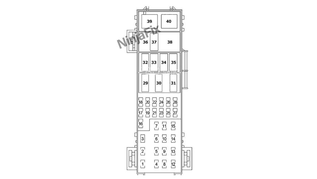
2007 Jeep Grand Cherokee under Hood Fuse Box and Relay Details
Assignment of the fuses in the Engine compartment(Power Distribution Center)
| Cavity | Cartridge Fuse | Mini Fuse | Description |
|---|---|---|---|
| 1 | 40 Amp Green | HVAC Blower | |
| 2 | 30 Amp Pink | Power Outlets | |
| 3 | 30 Amp Pink | Rr Wiper/Ign R/O | |
| 4 | 30 Amp Pink | ABS Pump | |
| 5 | 50 Amp Red | Cabin Htr 1 (Diesel Only) | |
| 6 | 50 Amp Red | Auto Shut Down (ASD) | |
| 7 | 30 Amp Pink | Rr HVAC (XK Only) | |
| 8 | 40 Amp Green | Acc Delay/Seats | |
| 9 | 40 Amp Green | Pwr Liftgate (XK Only) | |
| 10 | 40 Amp Green | Starter/Junction Block (JB) Power | |
| 11 | 30 Amp Pink | Cig Ltr/T-Tow | |
| 12 | 40 Amp Green | Rear Window Defog-ger (EBL)/Htd Mirror | |
| 13 | 40 Amp Green | Junction Block (JB) Power | |
| 14 | 50 Amp Red | Cabin Htr 2 (Diesel Only) | |
| 15 | 50 Amp Red | Cabin Htr 3 (Diesel Only) | |
| 16 | 25 Amp Natural | Integrated Power Module (IPM)/Coils | |
| 17 | Spare | ||
| 18 | 20 Amp Yellow | E ATX/AC Clutch | |
| 19 | 20 Amp Yellow | Ign Sw | |
| 20 | 20 Amp Yellow | PCM Batt (Gasoline Only) | |
| 21 | 30 Amp Green | ABS Valves | |
| 22 | 20 Amp Yellow | T-Tow (BUX) | |
| 23 | 20 Amp Yellow | Final Drive Control Module (FDCM) | |
| 24 | 20 Amp Yellow | Fuel Pump | |
| 25 | 20 Amp Yellow | Final Drive Control Module (FDCM) | |
| 26 | 15 Amp Blue | Powertrain Control Module (PCM) Auto Shut Down (ASD) (Diesel Only) | |
| 27 | 15 Amp Blue | Brake/Stop Lamps | |
| 28 | 25 Amp Natural | Next Generation Controller (NGC)/ Injectors | |
| 29 | Spare | ||
| 30 | Spare | ||
| 31 | Mini Relay | Cabin Htr 1 Rly (Diesel Only) | |
| 32 | Micro Relay | TCM Rly (Gasoline Only) | |
| 33 | Micro Relay | Starter Rly | |
| 34 | Micro Relay | AC Clutch Rly | |
| 35 | Micro Relay | Fuel Pump Rly | |
| 36 | Mini Relay | Cabin Htr 3 Rly (Diesel Only) | |
| 38 | Mini Relay | Cabin Htr 2 Rly (Diesel Only) | |
| 39 | Mini Relay | HVAC Blower Rly | |
| 40 | Mini Relay | ASD Rly |
Integrated Power Module
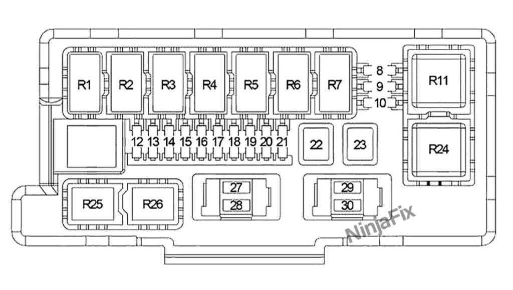
Assignment of the fuses in the Engine Compartment(Integrated Power Module)
| Cavity | Cartridge Fuse | Mini Fuse | Description |
|---|---|---|---|
| 8 | 10 Amp Red | Lt Park Lamps | |
| 9 | 10 Amp Red | Trailer-Tow Park Lamps | |
| 10 | 10 Amp Red | Rt Park Lamps | |
| 12 | 20 Amp Yellow | Front Control Module (FCM) Batt #4 | |
| 13 | 20 Amp Yellow | Front Control Module (FCM) Batt #2 | |
| 14 | 20 Amp Yellow | Adjustable Pedal | |
| 15 | 20 Amp Yellow | Ft Fog Lamps | |
| 16 | 20 Amp Yellow | Horn | |
| 17 | 20 Amp Yellow | Rear Wiper | |
| 18 | 20 Amp Yellow | Front Control Module (FCM) Batt #1 | |
| 19 | 20 Amp Yellow | Lt Trailer-Tow Stop/ Turn | |
| 20 | 20 Amp Yellow | Front Control Module (FCM) Batt #3 | |
| 21 | 20 Amp Yellow | Rt Trailer-Tow Stop/ Turn | |
| 22 | 30 Amp Pink | Final Drive Control Module (FDCM) MOD | |
| 23 | 50 Amp Red | Radiator Fan | |
| 27 | 15 Amp Blue | Ignition Off Draw (IOD) #1 | |
| 28 | 20 Amp Yellow | Ignition Off Draw (IOD) #2 | |
| 29 | 10 Amp Red | Occupant Restraint Controller (ORC) R/S | |
| 30 | 10 Amp Red | Occupant Restraint Controller (ORC) R/O | |
| Relay | |||
| R1 | Wiper (On/Off) | ||
| R2 | Wiper (High/Low) | ||
| R3 | Horn | ||
| R4 | Rear Fog Lamp | ||
| R5 | Trailer Tow (Left Turn) | ||
| R6 | Trailer Tow (Right Turn) | ||
| R7 | Park Lamp | ||
| R11 | Radiator Fan (High Speed) | ||
| R24 | Radiator Fan (Low Speed) | ||
| R25 | Front Fog Lamp | ||
| R26 | Adjustable Pedals |
WARNING: The terminal and harness assignments for individual connectors may vary depending on the vehicle’s equipment level, model, and market. It is recommended to refer to the fuse box diagram provided at the back of the fuse box cover for accurate information.
