Where are the Fuse Boxes located in the Can-Am Outlander?
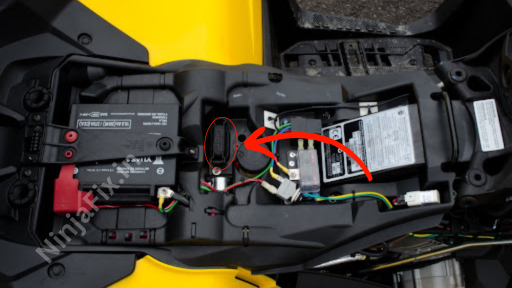
In the Can-Am Outlander, there are two fuse boxes: the main fuse box and the auxiliary fuse box. The main fuse box is situated under the console, while the auxiliary fuses can be found under the seat.
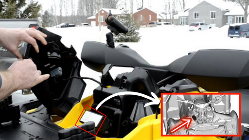
Can-Am Outlander Under Console Fuse Box and Relay Location
The auxiliary fuse box (If equipped) is located next to the interior fuse box. To open the lid, pull the tab in the direction as shown in the illustration.
Can-Am Under Seat Fuse Box Location
Can-AM Under Hood Fuse Box Layout
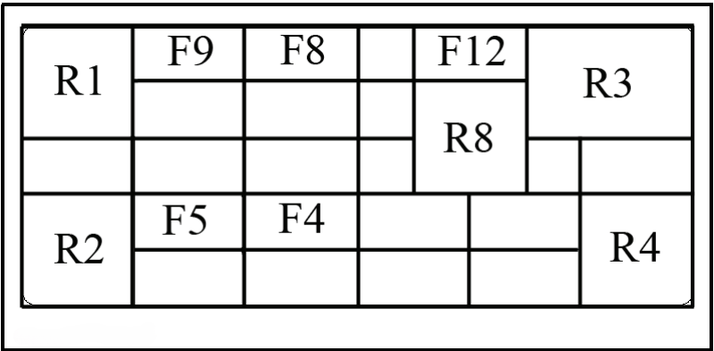
The layout of the fuse box can vary depending on the model of the vehicle. For the exact fuse layout, check inside the fuse box cover to determine the location of the fuses. Typically, the fuse box for the Can-Am Outlander looks like following:
Can-AM Fuse & Relay Box Layout
Can-AM Fuse & Relay Box
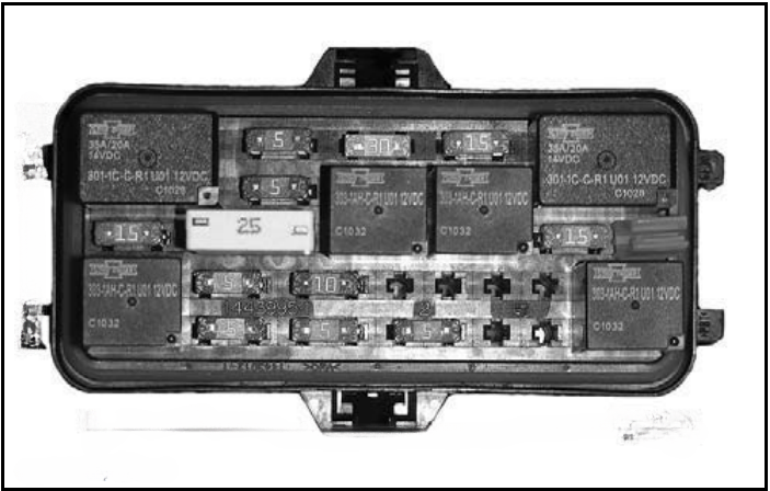
Can Am Outlander Fuse and Relay Relay Details:
The fuse box assignment for the Can-Am Outlander varies depending on the series, including the G2, G2L, and G3L. Additionally, it differs for variant models equipped with Electronic Throttle Control (ETC) and Mechanical Throttle Control (MTC). Please refer to your specific Outlander series and variant to ensure accurate fuse and relay assignments.
For G2 Series:
| Can Am Outlander G2 Series Covered Models: | |
| Outlander 1000 | Outlander 800 |
| Outlander 650 | |
| Auxiliary Fuse Box | |
| Fuse | Rating |
| Battery | 40 A |
| DPS Fuse | 40 A |
Models Equipped with Electronic Throttle Control (ETC) [1]:
| Main Fuse Box | ||
| Fuse & Relay No | Description | Rating |
| RY1 | Cooling Fan Relay | — |
| RY2 | Main Relay | — |
| RY3 | Lights Relay | — |
| RY5 | Accessory relay | — |
| RY6 | Brake relay | — |
| F1 | Start switch/Cluster | 10 A |
| F2 | Lights | 30 A |
| F3 | ACC 1 | 20 A |
| F4 | ACC 2 | 20 A |
| F5 | Fuel Pump/Injectors/Ignition coils/EVAP | 10 A |
| F6 | Cluster/Relays/DPS/Speed limiter | 10 A |
| F7 | Brake lights/Tail lights | 10 A |
| F8 | D.E.S.S/ECM | 10 A |
| F9 | 2WD/4WD | 10 A |
| F12 | Cooling fan (resettable) | 25 A |
Models Equipped with Mechanical Throttle Control (MTC) [2]:
| Main Fuse Box | ||
| Fuse & Relay No | Description | Rating |
| RY1 | Cooling Fan Relay | — |
| RY2 | Main Relay | — |
| RY3 | Accessory relay | — |
| RY4 | Fuel pump relay | — |
| RY5 | Lights relay | — |
| RY8 | Brake | — |
| F4 | Cluster/Relays/DPS | 5 A |
| F5 | Injectors/Ignition coils | 5 A |
| F6 | Inter-connector | 5 A |
| F7 | Winch | 5 A |
| F8 | D.E.S.S | 5 A |
| F9 | Cooling fan (resettable) | 25 A |
| F11 | Lights | 30 A |
| F12 | DC outlet | 15 A |
| F14 | Accessory | 15 A |
| F15 | Fuel pump | 5 A |
For G2L Series:
| Can Am Outlander G2L Series Covered Models: | |
| Outlander 450 | |
| Auxiliary Fuse Box | |
| Fuse | Rating |
| Battery | 40 A |
| DPS Fuse | 40 A |
| ABS Pump | 40 A |
| ABS Valves | 25 A |
| Accessories | 15 A (MTC Model) |
Models Equipped with Electronic Throttle Control (ETC) [3]:
| Main Fuse Box | ||
| Fuse & Relay No | Description | Rating |
| RY1 | Cooling Fan Relay | — |
| RY2 | Main Relay | — |
| RY3 | Lights Relay | — |
| RY4 | Trailer presence relay | — |
| RY5 | Accessory relay | — |
| RY6 | Brake relay | — |
| F1 | Start switch/Cluster | 10 A |
| F2 | Lights | 30 A |
| F3 | ACC 1 | 20 A |
| F4 | ACC 2 | 20 A |
| F5 | Fuel Pump/Injectors/Ignition coils/EVAP | 10 A |
| F6 | Cluster/Relays/DPS/Speed limiter | 10 A |
| F7 | Brake lights/Tail lights/ Flashers | 10 A |
| F8 | D.E.S.S/ECM | 10 A |
| F9 | 4WD/Lock actuator | 10 A |
| F10 | Hazard | 10 A |
| F11 | ABS valve | 25 A |
| F12 | Cooling fan (resettable) | 25 A |
Models Equipped with Mechanical Throttle Control (MTC) [4]:
| Main Fuse Box | ||
| Fuse & Relay No | Description | Rating |
| RY1 | Cooling Fan Relay | — |
| RY2 | Main Relay | — |
| RY3 | Accessory relay | — |
| RY4 | Fuel pump relay | — |
| RY8 | Brake | — |
| F4 | Cluster/Relays/DPS | 10 A |
| F5 | Injectors/Ignition coils | 10 A |
| F8 | Starter solenoid/ Key switch | 10 A |
| F9 | Cooling fan | 20 A |
| F12 | Headlamp/Accessories | 20 A |
For G3L Series:
| Can Am Outlander G3L Series Covered Models: | |
| Outlander Pro | Outlander 500 |
| Outlander 700 | |
| Auxiliary Fuse Box | |
| Fuse | Rating |
| Battery | 40 A |
| DPS Fuse | 40 A |
| ABS Pump | 40 A |
| ABS Valves | 25 A |
| Accessories | 15 A (MTC Model) |
Models Equipped with Electronic Throttle Control (ETC) [5]:
| Main Fuse Box | ||
| Fuse & Relay No | Description | Rating |
| RY1 | Main Relay | — |
| RY3 | Cooling fan relay | — |
| RY4 | Accessory relay | — |
| RY5 | Headlamp relay | — |
| F1 | Speed limiter ECM Start switch Gauge Ignition coil Inter-connector | 15 A |
| F2 | Accessories | 15 A |
| F3 | Headlamp | 7.5 A |
| F4 | Start switch Gauge | 10 A |
| F5 | Fuel pump | 10 A |
| F6 | 4WD actuator Oxygen sensor EVAP | 10 A |
| F7 | DPS DLC Brake lights | 15 A |
| F10 | Cooling fan (resettable) | 15 A |
Models Equipped with Mechanical Throttle Control (MTC) [6]:
| Main Fuse Box | ||
| Fuse & Relay No | Description | Rating |
| RY1 | Main Relay | — |
| RY2 | Brake relay | — |
| RY3 | Cooling fan relay | — |
| RY4 | Accessory relay | — |
| RY5 | Headlamp relay | — |
| RY6 | Fuel pump relay | — |
| F3 | Headlamp | 7.5 A |
| F4 | Inter-connector Gauge Key switch | 15 A |
| F5 | Fuel pump | 10 A |
| F6 | Ignition coil Inter-connector 4WD actuator | 10 A |
| F7 | DPS DLC Gauge Rear lights | 15 A |
| F10 | Cooling fan (resettable) | 15 A |
References
1. Can Am Outlander G2 Series (Electronic Throttle Control) Fusebox Diagram, PN: 193: Can Am Outlander Owner Manual G2 (Electronic Throttle Control) Series
2. Can Am Outlander G2 Series (Mechanical Throttle Control) Fusebox Diagram, PN: 195: Can Am Outlander Owner Manual G2 (Mechanical Throttle Control) Series
3. Can Am Outlander G2L Series (Electronic Throttle Control) Fusebox Diagram, PN: 161: Can Am Outlander Owner Manual G2L (Electronic Throttle Control) Series
4. Can Am Outlander G2L Series (Mechanical Throttle Control) Fusebox Diagram, PN: 171: Can Am Outlander Owner Manual G2L (Mechanical Throttle Control) Series
5. Can Am Outlander G3L Series (Electronic Throttle Control) Fusebox Diagram, PN: 264: Can Am Outlander Owner Manual G3L (Electronic Throttle Control) Series
6. Can Am Outlander G3L Series (Mechanical Throttle Control) Fusebox Diagram, PN: 300: Can Am Outlander Owner Manual G3L (Mechanical Throttle Control) Series

