The fuse box diagram for your Ford F-150 is a valuable resource, providing crucial details about the location and function of each fuse, enabling effective troubleshooting of electrical issues. However, owning a Ford F-150 entails much more than just dealing with electrical problems. As a proud owner, it’s essential to equip yourself with all the necessary information about your Ford F-150 to fully maximize your ownership experience.
Where are the fuse boxes located?
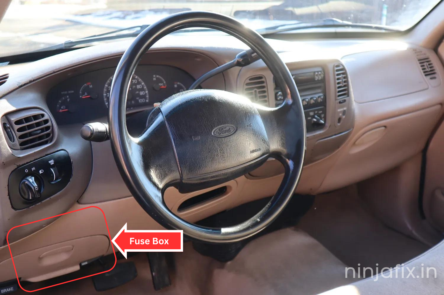
- Passenger Compartment : The fuse panel is located below and to the left of the steering wheel by the brake pedal behind the cover.
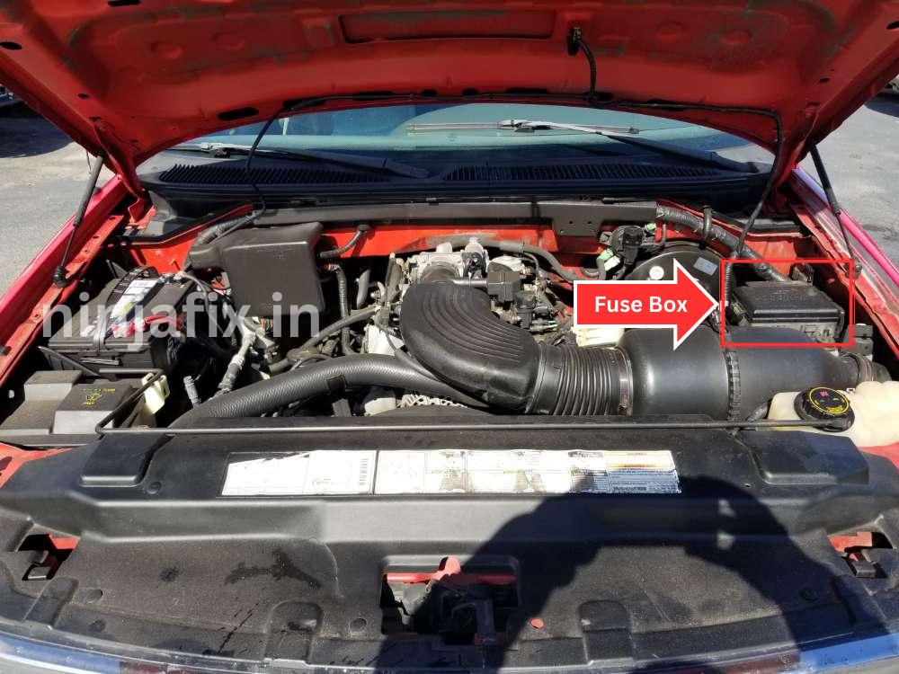
- Engine Compartment Fuse Box: The power distribution box is located in the engine compartment (left-side).
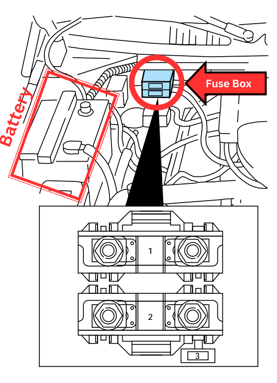
- Primary battery fuses (megafuses) : Primary battery fuses are located under the PRIMARY BATTERY FUSE cover next to starter relay.
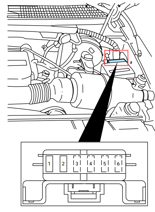
- Engine minifuse panel: The minifuse panel is located behind the power distribution box.
1. Passenger Compartment
2. Engine Compartment Fuse Box
3. Primary battery fuses
4. Engine minifuse panel
The minifuse panel is located behind the power distribution box.
1997 Ford F 150 Fuse Box Diagram
Passenger Compartment
1997 Ford F 150 Passenger Compartment Fuse Box Diagram
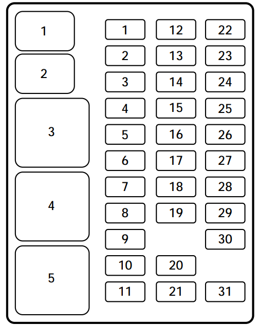
1997 Ford F 150 Passenger Compartment Fuse Details
| Position | Fuse Function |
|---|---|
| 1 | Stop/ turn lamps and turn indicators |
| 2 | Instrument cluster |
| 3 | Cigarette lighter |
| 4 | Power mirrors, autolamp, remote anti-theft/keyless entry, headlamp relay and parking lamp relay |
| 5 | Speed control, daytime running lamps, climate control blend door, backup lamps, A/C clutch coil |
| 6 | Brake-shift interlock, generic electronic module (GEM)/central timer module (CTM) and air suspension module |
| 7 | Not used |
| 8 | Radio, remote anti-theft/keyless entry, GEM module/CTM module |
| 9 | Not used |
| 10 | Not used |
| 11 | Wiper system |
| 12 | On-board diagnostic (OBD II) data link connector |
| 13 | Brake ON/OFF switch, rear anti-lock brake module and brake pressure switch |
| 14 | Interior lamps and accessory delay relay |
| 15 | GEM module/CTM module |
| 16 | High beam headlamps |
| 17 | Not used |
| 18 | Instrument illumination |
| 19 | Air bag diagnostic monitor, instrument cluster |
| 20 | GEM module/CTM module and powertrain control module (PCM) |
| 21 | Starter relay |
| 22 | Air bag diagnostic monitor and passenger air bag deactivate switch |
| 23 | 4WD clutch relay, electronic flasher, 4WD/2WD vacuum solenoids and trailer tow battery charge relay |
| 24 | I/P blower relay |
| 25 | 4WABS module and relay |
| 26 | Right low beam headlamp and DRL module |
| 27 | Foglamp relay |
| 28 | Left low beam headlamp |
| 29 | Autolamp, instrument cluster, transmission control indicator lamp and switch |
| 30 | Ignition coils and PCM relay |
| 31 | Not used |
| 1 | Interior lamps relay |
| 2 | Battery saver relay |
| 3 | Not used |
| 4 | One touch down relay |
| 5 | Accessory delay relay |
1997 Ford F150 fuse box diagram under hood
1997 Ford F 150 Power Distribution Fuse Box Diagram
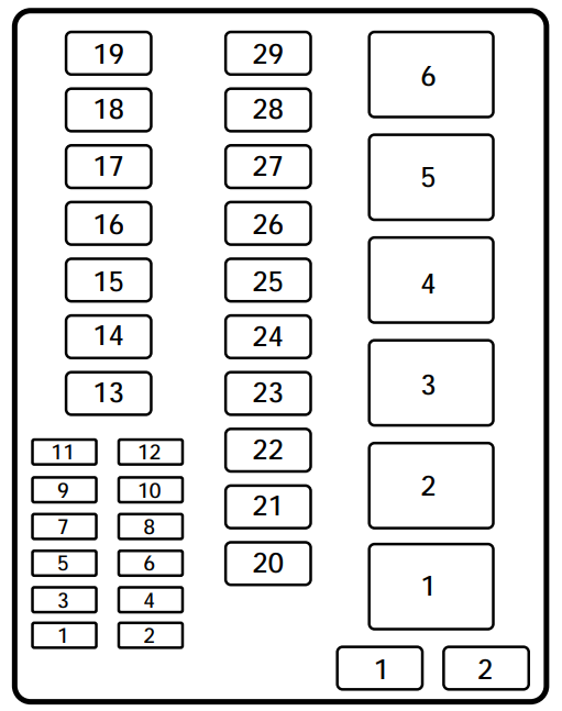
1997 Ford F 150 Power Distribution Fuse Box Details
| No | Fuse Function |
|---|---|
| 1 | Trailer tow back-up and tail lamps |
| 2 | Air bag diagnostic monitor |
| 3 | Power locks |
| 4 | Air suspension |
| 5 | Horn |
| 6 | Audio system |
| 7 | Parking and tail lamps |
| 8 | Headlamps |
| 9 | Daytime running lamps and fog lamps |
| 10 | Auxiliary power point |
| 11 | Not used |
| 12 | Not used |
| 13 | Not used |
| 14 | 4WABS/rear anti-lock brake |
| 15 | Air suspension compressor |
| 16 | Trailer tow battery charge and stop/turn lamps |
| 17 | 4WD transfer case shift motor and clutch |
| 18 | Driver power seat |
| 19 | Fuel pump |
| 20 | Instrument panel fuse panel ignition switch feed |
| 21 | Instrument panel fuse panel ignition switch feed |
| 22 | I/P fuse panel battery feed |
| 23 | I/P blower |
| 24 | PCM power |
| 25 | Power windows |
| 26 | Not used |
| 27 | Not used |
| 28 | Trailer tow electronic brake |
| 29 | Not used |
| 1 | Rear ABS diode |
| 2 | PCM diode |
| 1 | Windshield wipers HI/LO speed |
| 2 | Windshield wipers run/park relay |
| 3 | Washer pump relay |
| 4 | Fuel pump relay |
| 5 | Horn relay |
| 6 | PCM power relay |
Primary battery fuses
1997 Ford F 150 Primary Battery Fuse Box Diagram
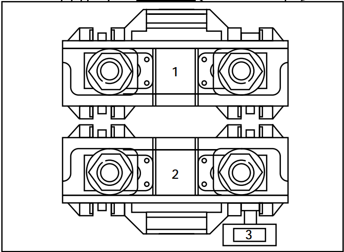
1997 Ford F 150 Primary Battery Fuse Details
| Fuse | Fuse Function |
|---|---|
| 1 | Power network box megafuse |
| 2 | Alternator megafuse |
| 3 | Alternator field minifuse |
Engine Minifuse Panel
1997 Ford F 150 Engine Mini Fuse Box Diagram
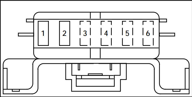
1997 Ford F 150 Engine Mini Fuse Details
| Fuse | Fuse Function |
|---|---|
| 1 | Powertrain control module (PCM) |
| 2 | Trailer tow stop/turn lamps |
| 3 | Not used |
| 4 | Not used |
| 5 | Not used |
| 6 | Not used |
WARNING: The terminal and harness assignments for individual connectors may vary depending on the vehicle’s equipment level, model, and market. It is recommended to refer to the fuse box diagram provided at the back of the fuse box cover for accurate information.

