Where are the fuse boxes located?
- Passenger compartment fuse panel / power distribution box : The fuse panel is located under the right-hand side of the instrument panel.
- Engine Compartment Relay Box: The power distribution box is located in the engine compartment (left-side).
1. Passenger Compartment

How to access fuse panel ?

Remove the trim panel and fuse box cover to access the fuses.
To remove the fuse box cover, place
a finger behind the PULL tab and
your thumb above the PULL tab as
shown in the illustration, then pull
the cover off.
2. Engine Compartment Fuse Box

2004 Ford F 150 Fuse Box Diagram
Passenger Compartment Fuse Panel / Power Distribution Box
2004 Ford F 150 Passenger Compartment Fuse Box Diagram

2004 Ford F 150 Passenger Compartment Fuse Details
| № | Amps | Fuse Function |
|---|---|---|
| 1 | 10 A | Run/Accessory – Wipers, Instrument cluster |
| 2 | 20 A | Stop/Turn lamps, Speed control deactivate switch |
| 3 | 5 A | Power mirrors, Memory logic power, Memory seats and pedals |
| 4 | 10 A | DVD battery power |
| 5 | 7.5 A | Keep alive memory for Powertrain Control Module (PCM) and climate control module |
| 6 | 15 A | Parklamps, BSM, Instrument panel illumination |
| 7 | 5 A | Radio (start signal) |
| 8 | 10 A | Heated mirrors, Switch indicator |
| 9 | — | Not used |
| 10 | 20 A | Trailer tow back-up lamps relay (PCB1), Trailer tow parklamp relay (R201) |
| 11 | 10 A | A/C clutch, 4×4 solenoid |
| 12 | — | Not used |
| 13 | 10 A | Climate control module power |
| 14 | 10 A | Back-up lamp and Daytime Running Lamps (DRL) relay coil, A/C pressure swatch, Brake-shift interlock solenoid |
| 15 | 5 A | Overdrive cancel, Cluster, Brake-Shift Interlock (BSI) |
| 16 | 10 A | ABS module (Run/Start power) |
| 17 | 15 A | Fog lamp relay (R202) |
| 18 | 10 A | Run/Start feed – Flasher relay, Electrochromatic mirror, Heated seats, BSM, Compass, RSS (Reverse Sensing System) |
| 19 | 10 A | Restraints (Air bag module) |
| 20 | 15 A | PCM 4×4 power |
| 21 | 15 A | Cluster keep alive power |
| 22 | 10 A | Delayed accessory power for audio, power door lock switch and moonroof switch illumination |
| 23 | 10 A | RH low beam headlamp |
| 24 | 15 A | Battery saver power for demand lamps |
| 25 | 10 A | LH low’ beam headlamp |
| 26 | 20 A | Horn relay (PCB3), Horn power |
| 27 | 5A | Passenger Air bag Deactivation (PAD) warning lamp, Cluster air bag warning lamp, Cluster RUN /START power |
| 28 | 5A | SecuriLock transceiver (PATS) |
| 29 | 15 A | PCM 4×4 power |
| 30 | — | Not used |
| 31 | 20 A | Radio power |
| 32 | 15 A | Vapor Management Valve (VMV), A/C clutch relay, Canister vent, Heated Exhaust Gas Oxygen (HEGO) sensors #11 and #21, CMCV, Mass Air Flow (MAF) sensor, VCT |
| 33 | 15 A | Shift solenoid, CMS #12 and #22 |
| 34 | 20 A | Fuel injectors and PCM power |
| 35 | 20 A | Instrument cluster high beam indicator, High beam headlamps |
| 36 | 10 A | Trailer tow right turn/stop lamps |
| 37 | 20 A | Rear power point |
| 38 | 25 A | Subwoofer power |
| 39 | 20 A | Instrument panel power point |
| 40 | 20 A | Low beam headlamps, DRL |
| 41 | 20 A | Cigar lighter, Diagnostic connector power |
| 42 | 10 A | Trailer tow left turn/stop lamps |
| 101 | 30A | Starter solenoid |
| 102 | 20A | Ignition switch feed |
| 103 | 20A | ABS valves |
| 104 | — | Not used |
| 105 | 30A | Electric trailer brakes |
| 106 | 30A | Trailer tow battery charge |
| 107 | 30A | Power door locks (BSM) |
| 108 | 30A | Passenger power seat |
| 109 | 30A | Driver power seat, Adjustable pedals |
| 110 | — | Not used |
| 111 | 30A | 4×4 relays |
| 112 | 40A | ABS pump power |
| 113 | 30A | Wipers and washer pump |
| 114 | 40A | Heated backlite, Heated mirror power |
| 115 | — | Not used |
| 116 | 30A | Blower motor |
| 117 | — | Not used |
| 118 | 30A | Heated seats |
| 401 | 30A Circuit breaker | Power windows, Moonroof, Power sliding backlite |
| R01 | Full ISO relay | Starter solenoid |
| R02 | Full ISO relay | Accessory delay |
| R03 | Full ISO relay | Hi-beam headlamps |
| R04 | Full ISO relay | Heated backlite |
| R05 | Full ISO relay | Trailer tow battery charge |
| R06 | Full ISO relay | Blower motor |
| R201 | Half ISO relay | Trailer tow park lamps |
| R202 | Half ISO relay | Fog lamps |
| R203 | Half ISO relay | PCM |
2004 Ford F 150 Relay Box diagram under hood
2004 Ford F 150 Relay Box Diagram
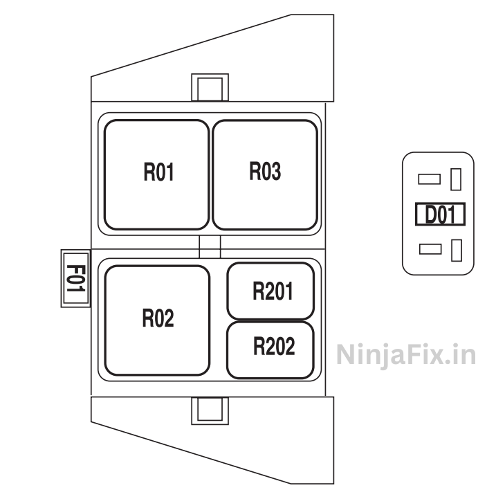
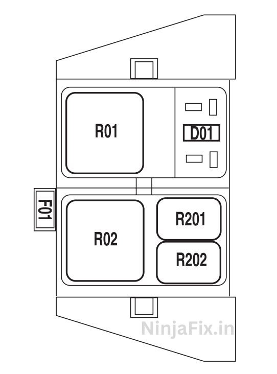
2004 Ford F 150 Relay Box Details
| No | Amps | Fuse Function |
|---|---|---|
| F01 | 5A | Clockspring illumination |
| R01 | — | 4×4 CCW |
| R02 | — | 4×4 CW |
| R03 | — | Daytime Running Lamps (DRL) (if equipped, otherwise not used) |
| R201 | — | DRL |
| R202 | — | A/C clutch |
| D01 | — | A/C clutch diode |
WARNING: The terminal and harness assignments for individual connectors may vary depending on the vehicle’s equipment level, model, and market. It is recommended to refer to the fuse box diagram provided at the back of the fuse box cover for accurate information.