The Audi A6 C8 represents the fifth generation of the Audi A6, released in the year 2019, 2020, 2021, 2022, 2023, and 2024. Find detailed information about the fuses in the Audi A6 C8, including box diagrams and their respective locations.
Where are the Fuse Boxes located in Audi A6 C8 ?
The 5th generation Audi A6 C8 features a total of three fuse panels. Two of these fuse panels are located in the passenger compartment, while the third one is situated in the luggage box or trunk area.
Learn more about the Fuse Box Diagram of Audi A6 for other generation.
Audi A6 C8 Under Dash Fuse Box and Relay Location
In left-hand drive vehicles, you can find the fuses under the footrest in the left footwell. On the other hand, in right-hand drive vehicles, the fuses are located behind a cover, typically on the left front side of the cockpit.
Audi A6 C8 Fuse Box location in Luggage Compartment
In the Audi A6 C8, there is an additional fuse panel located in the luggage compartment floor.
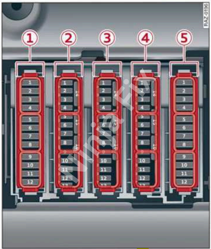
Audi A6 C8 Under Dash Fuse Box Layout
Audi A6 C8 Under Dash Fuse and relay Box Diagram
Fuse box No. – 1
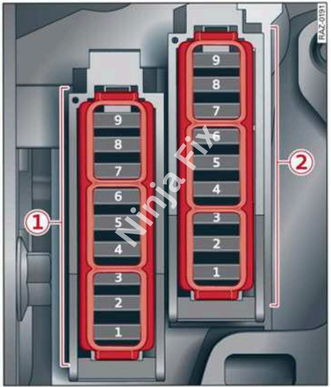
Fuse box No. – 2
Audi A6 C8 Under Dash Fuse and relay Box Details
Fuse box no. – 1 Location: Left side of the cockpit: Fuse panel with plastic Clip.
| Fuse No | Functions |
| Fuse panel 1 (black) | |
| 2 | Steering column adjustment |
| 3 | DVD drive |
| 4 | Steering column electronics |
| 5 | Light switch, switch panels |
| 6 | Volume control |
| 7 | Instrument cluster |
| 8 | Upper/lower display |
| 9 | Steering wheel heating |
| Fuse panel 2 (brown) | |
| 2 | Infotainment system |
| 3 | USB ports with charging function |
| 4 | Head-up display |
| 5 | Climate control system, fragrance system, ionizer |
| 9 | Steering column lock |
Fuse box no. – 2
| No | Functions |
| Fuse panel 1 (black) | |
| 2 | Engine components, coolant pump, oxygen sensor |
| 3 | Exhaust doors, fuel injectors, air intake, motor heating |
| 4 | Hot water pump, exhaust doors, NOX sensors, particulate sensor, biodiesel sensor |
| 5 | Brake light sensor |
| 6 | Engine valves, camshaft adjustment |
| 7 | Heated oxygen sensor, mass airflow sensor |
| 8 | High pressure pump, engine mount, coolant pump, fuel pressure regulator |
| 9 | Engine components, 48 V coolant pump, 48 V starter generator |
| 10 | Oil pressure sensor, oil temperature sensor |
| 11 | 48 V coolant pump, 48 V starter generator, 12 V starter generator |
| 12 | Engine valves, engine mount |
| 13 | Engine cooling |
| 14 | Engine control module, fuel injectors |
| 15 | Ignition coils, oxygen sensors, charge air cooling |
| 16 | Fuel pump |
| Fuse panel 2 (red) | |
| 1 | Anti-theft alarm system |
| 2 | Drive system control module |
| 3 | Left front lumbar support |
| 4 | Electronic toll collection system (ETC) |
| 5 | Horn |
| 6 | Parking brake |
| 7 | Diagnostic interface |
| 8 | Roof electronics control module |
| 9 | Driver assistance systems control module |
| 10 | Airbag control module |
| 11 | Electronic Stabilization Control (ESC), Anti-Lock Braking System (ABS) |
| 12 | Diagnostic connector, light/rain sensor |
| 13 | Climate control system, vehicle electrical system control module |
| 14 | Right front door control module |
| 15 | Climate control system compressor, vehicle electrical system control module |
| 16 | Auxiliary battery control module, brake system pressure reservoir |
| Fuse panel 3 (red) | |
| 1 | Ignition coils |
| 5 | Engine mount |
| 6 | Transmission fluid pump |
| 7 | Instrument panel |
| 8 | Climate control system blower |
| 9 | Windshield wiper control module |
| 10 | Dynamic steering |
| 11 | Engine start |
| 12 | Automatic transmission fluid pump |
| Fuse panel 4 (black) | |
| 1 | Front seat heating |
| 2 | Windshield wipers |
| 3 | Left headlight electronics |
| 4 | Panoramic glass roof |
| 5 | Left front door control module |
| 6 | Sockets |
| 7 | Right rear door control module |
| 8 | All wheel drive control module |
| 9 | Right headlight electronics |
| 10 | Windshield washer system/headlight washer system control module |
| 11 | Left rear door control module |
| 12 | Auxiliary heating, exterior sound generator |
| Fuse panel 5 (brown) | |
| 1 | Seat ventilation, seat electronics, rearview mirror, rear climate control system control panel, diagnostic connection, traffic information antenna (TMC) |
| 2 | Vehicle electrical system control module, diagnostic interface |
| 3 | Engine sound control module |
| 4 | Transmission heating valve |
| 5 | Engine start |
| 7 | Active accelerator pedal |
| 8 | Night vision assist |
| 9 | Adaptive cruise control, front wheel sensors |
| 11 | Intersection assistant, driver assist systems |
| 12 | Exterior sound generator |
| 15 | USB connection |
Audi A6 C8 Luggage Fuse Box Layout
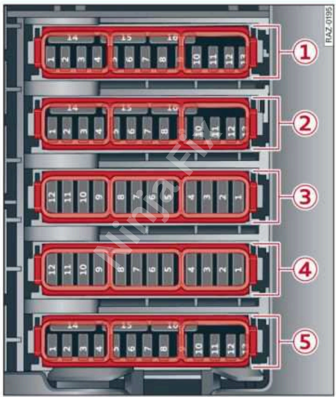
Audi A6 C8 Luggage Fuse and Relay Box Diagram
Audi A6 C8 Luggage Fuse and Relay Box Details
| No | Functions |
| Fuse panel 1 (black) | |
| 1 | Thermal management |
| 3 | Passenger’s side rear safety belt tensioner |
| 4 | Driver’s side rear safety belt tensioner |
| 5 | Air suspension/suspension control |
| 6 | Automatic transmission control module |
| 7 | Rear sliding sunroof, rear spoiler |
| 8 | Rear seat heating |
| 9 | Convenience system control module, left tail lights |
| 10 | Front belt tensioner on driver’s side |
| 11 | Luggage compartment lid central locking, fuel filler door, convenience system control module, sunshade, luggage compartment cover |
| 12 | Luggage compartment lid control module |
| Fuse panel 2 (red) | |
| 1 | Suspension stabilization control module |
| 2 | Service disconnect switch |
| 4 | Electric drive system, power electronics |
| 5 | Brake system, brake booster |
| 6 | High-voltage battery coolant pump |
| 7 | Auxiliary climate control |
| 8 | Climate control system compressor |
| 9 | Auxiliary battery control module |
| 10 | High-voltage battery |
| 11 | High-voltage charger |
| 14 | Thermal management, coolant pumps |
| 15 | Thermal management |
| Fuse panel 3 (brown) | |
| 1 | Driver assistance systems control module |
| 2 | Audi phone box |
| 3 | Right lumbar support |
| 4 | Side assist |
| 5 | Rear Seat Remote |
| 6 | Tire pressure monitoring system |
| 7 | Emergency call and communication control module |
| 8 | Auxiliary heating radio receiver, tank module |
| 9 | Automatic transmission selector lever |
| 10 | TV tuner, data exchange and telematics control module |
| 11 | Convenience access and start authorization control module |
| 12 | Garage door opener |
| 13 | Rearview camera, peripheral cameras |
| 14 | Convenience system control module, right tail lights |
| 16 | Front belt tensioner on front passenger’s side |
| Fuse panel 4 (black) | |
| Not assigned | |
| Fuse panel 5 (red) | |
| 2 | Exterior antenna |
| 3 | Exhaust treatment, engine sound control module |
| 4 | Rear climate control system control panel |
| 5 | Right trailer hitch light, right rear seat adjustment |
| 7 | Trailer hitch release |
| 8 | Left trailer hitch light, right rear seat adjustment |
| 9 | Trailer hitch socket, high-voltage battery |
| 10 | All wheel drive control module, sport differential |
| 11 | Exhaust treatment |
WARNING: The terminal and harness assignments for individual connectors may vary depending on the vehicle’s equipment level, model, and market. It is recommended to refer to the fuse box diagram provided at the back of the fuse box cover for accurate information.