Where are the Fuse Boxes located in the 2013 GMC Sierra?
2013 GMC Sierra has 2 main boxes with fuses and relays. One is in the cabin (Passenger Compartment) and another is under the hood (Engine Compartment).
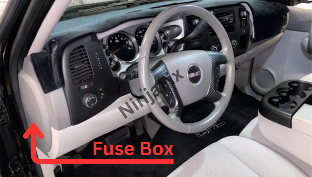
2013 GMC Sierra Under Dash Fuse Box and Relay Location
The Fuse and Relay box is located under the dashboard, on the driver side, below the steering, and is covered with trim.
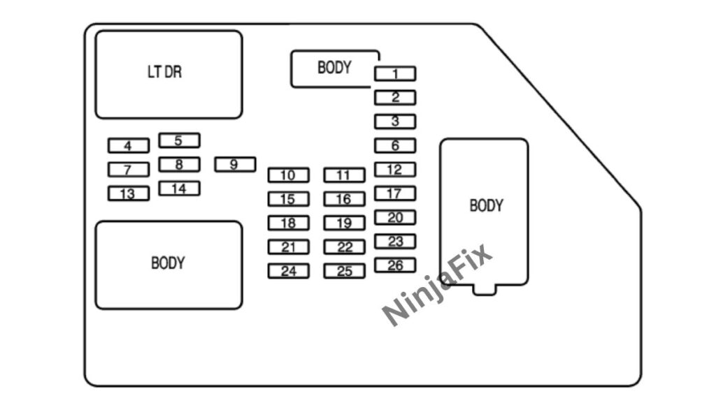
2013 GMC Sierra under Dash Fuse Box Layout
2013 GMC Sierra under Dash Fuse and relay Box Diagram
Instrument Panel Fuse Block
The Fuse Block access door is on the Driver’s side edge of the Instrument Panel. Pull off the cover to access to fuse block
2013 GMC Sierra Under Dash Fuse and relay Box Details
Assignment of the fuses in the Instrument Panel Fuse Block
| No. | Usage |
|---|---|
| 1 | Rear Seats |
| 2 | Rear Accessory Power Outlet |
| 3 | Steering Wheel Controls Backlight |
| 4 | Driver Door Module |
| 5 | Dome Lamps, Driver’s Side Turn Signal |
| 6 | Driver Side Turn Signal, Stoplamp |
| 7 | Instrument Panel Back Lighting |
| 8 | Passenger Side Turn Signal, Stoplamp |
| 9 | Universal Home Remote |
| 10 | Power Door Lock 2 (Unlock Feature) |
| 11 | Power Door Lock 2 (Lock Feature) |
| 12 | Stoplamps, Center-High Mounted Stoplamp |
| 13 | Rear Climate Controls |
| 14 | Power Mirror |
| 15 | Body Control Module (BCM) |
| 16 | Accessory Power Outlets |
| 17 | Interior Lamps |
| 18 | Power Door Lock 1 (Unlock Feature) |
| 19 | Rear Seat Entertainment |
| 20 | Ultrasonic Rear Parking Assist |
| 21 | Power Door Lock 1 (Lock Feature) |
| 22 | Driver Information Center (DIC) |
| 23 | Not Used |
| 24 | Not Used |
| 25 | Driver Seat Module, Remote Keyless Entry System |
| 26 | Driver Power Door Lock (Unlock Feature) |
| Circuit Breaker | |
| LT DR | Driver’s Side Power Window Circuit Breaker |
| Harness Connector | |
| LT DR | Driver’s Door Harness Connection |
| BODY | Harness Connector |
| BODY | Harness Connector |
Center Instrument Panel Block
The center instrument utility block is located underneath the instrument panel, to the left of the steering column.
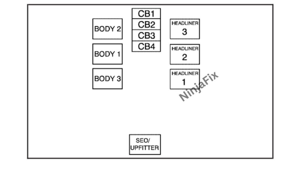
Assignment of the fuses in the Center Instrument Panel Fuse Block
| Harness Connector | Usage |
|---|---|
| BODY 2 | Body Harness Connector 2 |
| BODY 1 | Body Harness Connector 1 |
| BODY 3 | Body Harness Connector 3 |
| HEADLINER 3 | Headliner Harness Connector 3 |
| HEADLINER 2 | Headliner Harness Connector 2 |
| HEADLINER 1 | Headliner Harness Connector 1 |
| SEO/UPFITTER | Special Equipment Option Upfitter Harness Connector |
| Circuit Breaker | |
| CB1 | Passengers Side Power Window Circuit Breaker |
| CB2 | Passengers Seat Circuit Breaker |
| CB3 | Drivers Seat Circuit Breaker |
| CB4 | Rear Sliding Window |
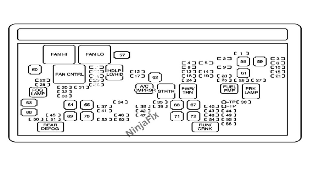
2013 GMC Sierra Under Hood Fuse and Relay box location
The Under Hood Fuse Block in the Engine Compartment on the driver’s side of the vehicle near the battery. Lift the cover for access to the fuse/relay block.

Auxiliary Electric Cooling Fan Fuse Block
The auxiliary electric cooling fan fuse block is located in the engine compartment on the driver’s side of the vehicle next to the under hood fuse block.
2013 GMC Sierra Under Hood Fuse Box Layout
2013 GMC Sierra under Hood Fuse and relay Box Diagram
2013 GMC Sierra under hood Fuse Box Details
Assignment of the fuses in the Engine compartment
| No. | Usage |
|---|---|
| 1 | Right Trailer Stop/Turn Lamp |
| 2 | Electronic Stabiity Suspension Control, Automatic Level Control Exhaust |
| 3 | Left Trailer Stop/Turn Lamp |
| 4 | Engine Controls |
| 5 | Engine Control Module, Throttle Control |
| 6 | Trailer Brake Controller |
| 7 | Front Washer |
| 8 | Oxygen Sensors |
| 9 | Anti-lock Brakes System 2 |
| 10 | Trailer Back-up Lamps |
| 11 | Driver’s Side Low-Beam Headlamp |
| 12 | Engine Control Module (Battery) |
| 13 | Fuel Injectors, Ignition Coils (Right Side) |
| 14 | Transmission Control Module (Battery) |
| 15 | Vehicle Back-up Lamps |
| 16 | Passenger’s Side Low-Beam Headlamp |
| 17 | Air Conditioning Compressor |
| 18 | Oxygen Sensors |
| 19 | Transmission Controls (Ignition) |
| 20 | Fuel Pump |
| 21 | Fuel System Control Module |
| 22 | Not Used |
| 23 | Not Used |
| 24 | Fuel Injectors, Ignition Coils (Left Side) |
| 25 | Trailer Park Lamps |
| 26 | Driver’s Side Park Lamps |
| 27 | Passenger’s Side Park Lamps |
| 28 | Fog Lamps |
| 29 | Horn |
| 30 | Passenger’s Side High-Beam Headlamp |
| 31 | Daytime Running Lamps |
| 32 | Driver’s Side High-Beam Headlamp |
| 33 | Daytime Running Lights 2 |
| 34 | Sunroof |
| 35 | Key Ignition System, Theft Deterrent System |
| 36 | Windshield Wiper |
| 37 | SEO B2 Upfitter Usage (Battery) |
| 38 | Electric Adjustable Pedals |
| 39 | Climate Controls (Battery) |
| 40 | Airbag System (Ignition) |
| 41 | Amplifier |
| 42 | Audio System |
| 43 | Miscellaneous (Ignition), Cruise Control |
| 44 | Not Used |
| 45 | Airbag System (Battery) |
| 46 | Instrument Panel Cluster |
| 47 | Power Take-Off |
| 48 | Auxiliary Climate Control (Ignition), Compass-Temperature Mirror |
| 49 | Center High-Mounted Stoplamp (CHMSL) |
| 50 | Rear Defogger |
| 51 | Heated Mirrors |
| 52 | SEO B1 Upfitter Usage (Battery) |
| 53 | Cigarette Lighter, Auxiliary Power Outlet |
| 54 | Automatic Level Control Compressor Relay, SEO Upfitter Usage |
| 55 | Climate Controls (Ignition) |
| 56 | Engine Control Module, Secondary Fuel Pump (Ignition) |
| J-Case | |
| 57 | Cooling Fan 1 |
| 58 | Nit Used |
| 59 | Heavy Duty AntMock Brake System |
| 60 | Cooling Fan 2 |
| 61 | Anti-lock Brake System 1 |
| 62 | Starter |
| 63 | Stud 2 {Trailer Brakes) |
| 64 | Left Bussed Electrical Center 1 |
| 65 | Not Used |
| 66 | Heated Windshield Washer System |
| 67 | Four-Wheel Drive System |
| 68 | Stud 1 (Trailer Connector Battery Power) (Optional – 40A Fuse Required) |
| 69 | Mid-Bussed Electrical Center 1 |
| 70 | Climate Control Blower |
| 71 | Not Used |
| 72 | Left Bussed Electrical Center 2 |
| Relays | |
| FAN HI | Cooling Fan High Speed |
| FAN LO | Cooling Fan Low Speed |
| ENG EXH VLV | Not Used |
| FAN CNTRL | Cooling Fan Control |
| HDLP LO/HID | Low-Beam Headlamp |
| FOG LAMP | Front Fog Lamps |
| A/C CMPRSR | Air Conditioning Compressor |
| STRTR | Starter |
| PWR/TRN | Powertrain |
| FUEL PMP | Fuel Pump |
| PRK LAMP | Parking Lamps |
| REAR DEFOG | Rear Defogger |
| RUN/CRANK | Switched Power |
Auxiliary box(Engine Compartment
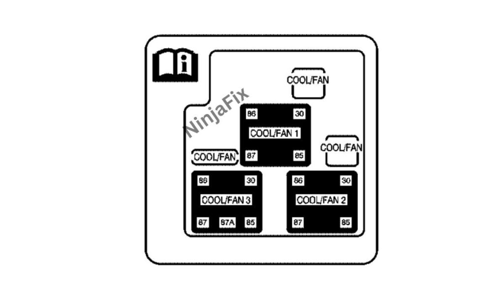
Assignment of the fuses in the Engine compartment auxiliary box
| Name | Description |
|---|---|
| COOL/FAN | Cooling Fan |
| COOL/FAN | Cooling Fan Relay Fuse |
| COOL/FAN | Cooling Fan Fuse |
| Relays | |
| COOL/FAN 1 | Cooling Fan Relay 1 |
| COOL/FAN 3 | Cooling Fan Relay 3 |
| COOL/FAN 2 | Cooling Fan Relay 2 |
WARNING: The terminal and harness assignments for individual connectors may vary depending on the vehicle’s equipment level, model, and market. It is recommended to refer to the fuse box diagram provided at the back of the fuse box cover for accurate information.