Where are the Fuse Boxes located in the 2011 Toyota Tacoma?
2011 Toyota Tacoma has 2 main boxes with fuses and relays. One is in the cabin (Passenger Compartment) and another is under the hood (Engine Compartment).
2011 Toyota Tacoma Under Dash Fuse Box and Relay Location
The Fuse and Relay box is located under the dashboard, on the passenger side, below the glove box, and is covered with trim.
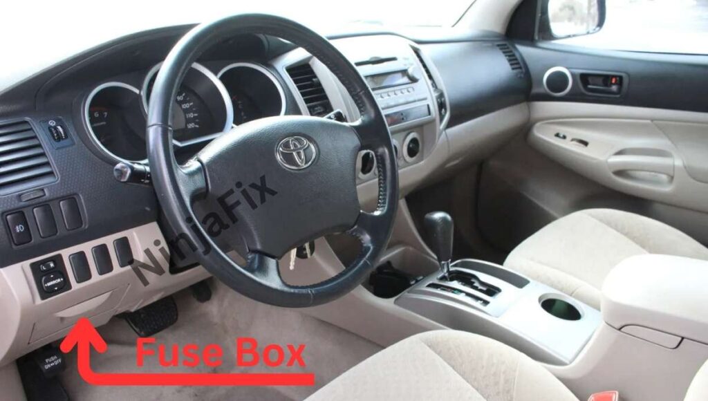
The fuse box is located in the driver’s side of the instrument panel, behind the storage compartment.
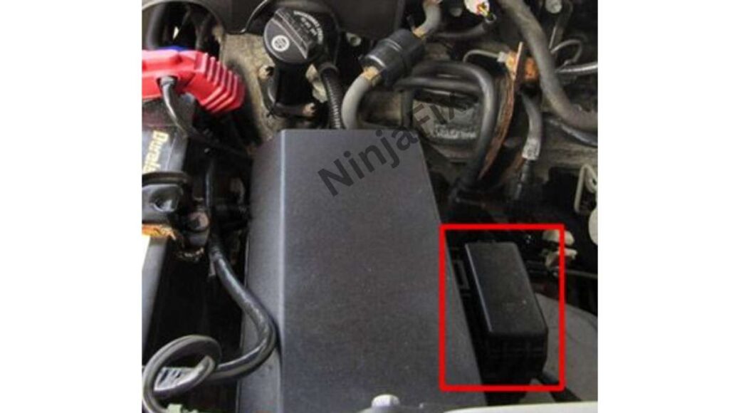
2011 Toyota Tacoma Under Hood Fuse and Relay box location
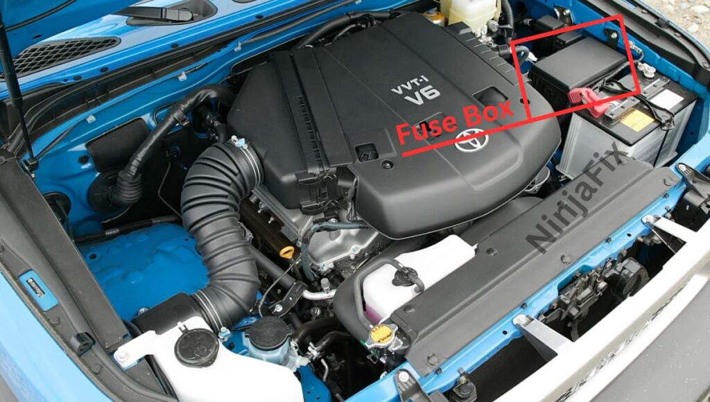
The engine compartment fuse block is in the engine compartment is located on the driver side of vehicle.
2011 Toyota Tacoma under Dash Fuse Box Layout
2011 Toyota Tacoma under Dash Fuse and relay Box Diagram

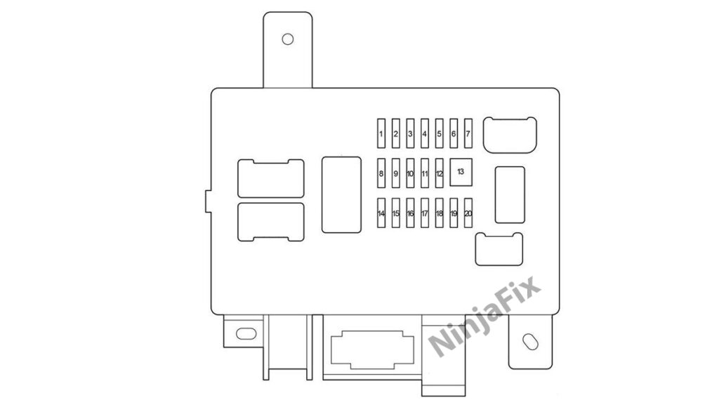
2011 Toyota Tacoma under Dash Fuse and relay Box Details
Assignment of the fuses in the Passenger Compartment
| No. | Name | Amp(A) | Designation |
|---|---|---|---|
| 1 | IGN | 15 | Multiport fuel injection system/ sequential multiport fuel injection system, anti-lock brake system, traction control system, vehicle stability control system, SRS airbag system, front passenger occupant classification system, engine immobilizer system |
| 2 | GAUGE | 7.5 | Meter and gauge, emergency flashers, front passenger’s seat belt warning system |
| 3 | TAIL | 10 | Tail lights, license plate lights, parking lights, multiport fuel injection system/sequential multiport fuel injection system, front fog lights, instrument panel light control, illuminations |
| 4 | – | – | Not used |
| 5 | ACC | 7.5 | Shift lock system, outside rear view mirrors, audio system, power outlets |
| 6 | PWR OUTLET | 15 | Power outlets |
| 7 | DR LCK | 20 | Door lock system |
| 8 | IG1 NO.2 | 10 | Anti-lock brake system, vehicle stability control system, stop lights, charging system, multiport fuel injection system/sequential multiport fuel injection system, air conditioning system, instrument panel light control, anti-glare inside rear view mirror, back monitor, clutch start cancel switch, rear differential lock system, power outlets, tire pressure warning system |
| 9 | BKUP LP | 10 | Trailer lights (back-up lights) |
| 10 | IG1 | 10 | Anti-lock brake system, traction control system, vehicle stability control system, backup lights, air conditioning system, shift lock system, audio system, passenger airbag manual on-off switch |
| 11 | P RR P/W | 20 | Rear passenger’s power window (right side) |
| 12 | P FR P/W | 20 | Front passenger’s power window |
| 13 | D FR P/W | 30 | Power windows |
| 14 | WSH | 10 | Wipers and washer |
| 15 | D RR P/W | 20 | Rear passenger’s power window (left side) |
| 16 | 4WD | 20 | Four-wheel drive system, rear differential lock system |
| 17 | WIP | 30 | Wipers and washer |
| 18 | – | – | Not used |
| 19 | – | – | Not used |
| 20 | – | – | Not used |

| No. | Relay |
|---|---|
| R1 | Taillights |
| R2 | Power windows |
| R3 | Accessory socket |
2011 Toyota Tacoma Under Hood Fuse Box Layout
2011 Toyota Tacoma under Hood Fuse and relay Box Diagram
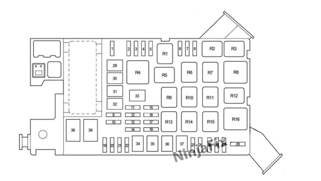
2011 Toyota Tacoma under hood Fuse and Relay Box Details
Assignment of the fuses and relay in the Engine Compartment
| No. | Name | Amp(A) | Designation |
|---|---|---|---|
| 1 | A/C | 10 | Air conditioning system |
| 2 | FR FOG | 15 | 2005-2011: Front fog lights |
| 2 | TOWING TAIL | 30 | 2012-2015: Trailer lights (tail lights) |
| 3 | TOWING TAIL | 30 | 2005-2011: Trailer lights (tail lights) |
| 3 | FOG FR | 15 | 2012-2015: Front fog lights |
| 4 | STOP | 10 | Stop lights, high mounted stop light, vehicle stability control system, anti-lock brake system, shift lock system, multiport fuel injection system/sequential multiport fuel injection system, towing converter |
| 5 | OBD | 7.5 | 2005-2011: On-board diagnosis system |
| 5 | TOWING BRK | 30 | Trailer brake controller |
| 6 | – | – | Not used |
| 7 | EFI NO.2 or EFI | 10 | Multiport fuel injection system/sequential multiport fuel injection system |
| 8 | S/HTR NO.2 | 30 | 2013-2015: Seat heaters |
| 9 | TOWING BRK | 30 | 2005-2011: Trailer brake controller |
| 9 | OBD | 7.5 | 2012-2015: On-board diagnosis system |
| 10 | BATT CHG | 30 | Trailer sub battery |
| 11 | AIR PMP HTR | 10 | 2013-2015: AI system |
| 12 | TOWING | 30 | Towing converter |
| 13 | TURN & HAZ | 15 | Turn signal lights, emergency flashers, meter and gauge |
| 14 | RADIO NO.2 | 30 | Audio system |
| 15 | HEAD (LO RH) | 10 | Right-hand headlight (low beam), front fog lights (2012-2015) |
| 16 | HEAD (LO LH) | 10 | Left-hand headlight (low beam), front fog lights (2005-2010) |
| 17 | HEAD (HI RH) | 10 | Right-hand headlight (high beam) |
| 18 | HEAD (HI LH) | 10 | Left-hand headlight (high beam), meter and gauge |
| 19 | ETCS | 10 | Multiport fuel injection system/sequential multiport fuel injection system, electronic throttle control system |
| 20 | ALT-S | 7.5 | Charging system |
| 21 | EFI or EFI-MAIN | 20 | Multiport fuel injection system/sequential multiport fuel injection system |
| 22 | HORN | 10 | Horn |
| 23 | A/F HTR | 15 | Multiport fuel injection system/sequential multiport fuel injection system |
| 24 | – | – | Not used (Short Pin) |
| 25 | ECU-B | 7.5 | Wireless remote control system, air conditioning system, multiplex communication system, meter and gauge, front passenger occupant classification system, garage door opener |
| 26 | DOME | 7.5 | Interior light, personal lights, clock, vanity lights |
| 27 | RADIO NO.1 | 10 | 2005-2012: Audio system |
| 27 | RADIO NO.1 | 20 | 2013-2015: Audio system |
| 28 | STA | 7.5 | Starting system, multiport fuel injection system/sequential multiport fuel injection system, meter and gauge, clutch start cancel switch |
| 29 | S/HTR NO.1 | 50 | 2013-2015: Seat heaters |
| 30 | J/B | 50 | “TAIL”, “AC SKT”, “DR LCK”, “D FR P/W”, “D RR P/W”, “P FR P/W”, “P RR P/W” fuses |
| 31 | AM1 | 50 | “ACC”, “IG1”, “TGI NO.2”, “WIP”, “WSH”, “4WD”, “STA”, “BKUP LP” fuses |
| 32 | HTR | 50 | “A/C” fuse, air conditioning system |
| 33 | ABS NO.1 | 50 | Anti-lock brake system, vehicle stability control system |
| 34 | AM2 | 30 | “IGN”, “GAUGE” fuses, multiport fuel injection system/sequential multiport fuel injection system |
| 35 | AIR PMP | 50 | Multiport fuel injection system/sequential multiport fuel injection system |
| 36 | ABS NO.2 | 30 | Anti-lock brake system, vehicle stability control system |
| 37 | – | – | Not used |
| 38 | AC SKT | 100 | 2005-2012: Cigarette lighter, power outlets |
| 38 | INV | 100 | 2013-2015: Power outlets |
| 39 | ALT | 120 | without towing package: “AM1”, “AC SKT”, “HEATER”, “FR FOG”, “STOP”, “OBD”, “J/B”, ‘TOWING TAIL”, “TOWING BRK”, “BATT CHG” fuses |
| 39 | ALT | 140 | with towing package: “AM1”, “AC SKT”, “HEATER”, “FR FOG”, “STOP”, “OBD”, “J/B”, “TOWING TAIL”, “TOWING BRK”, “BATT CHG” fuses |
| Relay | |||
| R1 | Not used | ||
| R2 | Towing tail relay | ||
| R3 | Stop lamp control (with VSC) | ||
| R4 | Headlight | ||
| R5 | Front fog light (1GR-FE) | ||
| R6 | Circuit Opening | ||
| R7 | Air Fuel Sensor Heater | ||
| R8 | Dimmer | ||
| R9 | Not used | ||
| R10 | Fuel pump (1GR-FE) | ||
| R11 | Air conditioning (MG CLT – magnetic clutch) | ||
| R12 | Starter | ||
| R13 | Main relay (EFI) | ||
| R14 | Trailer sub battery | ||
| R15 | Horn | ||
| R16 | Heater |
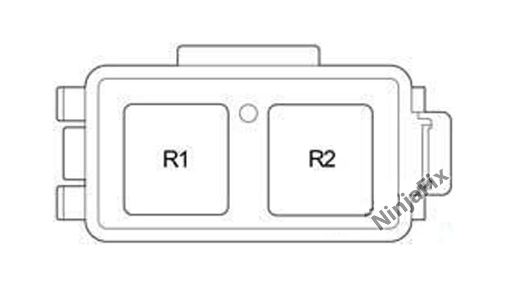
| No. | Relay |
|---|---|
| R1 | Not used |
| R2 | Accessory socket |
WARNING: The terminal and harness assignments for individual connectors may vary depending on the vehicle’s equipment level, model, and market. It is recommended to refer to the fuse box diagram provided at the back of the fuse box cover for accurate information.